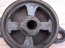
How Houdailles Work
The rotor and stator divide the cavity in the shock body into four chambers, one on each side of the two rotor vanes. Operation consists of pumping oil between two full and partially empty working chambers. The oil passes through ports cross-drilled in the rotor hub and past a the restriction imposed by an adjustable needle valve.
The shock works in both directions of rotation to dampen spring oscillations on joust and rebound. Unless some additional hardware is included, the dampening force is equal in both directions.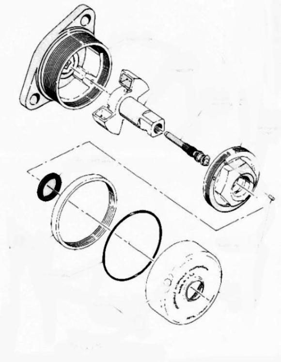
Most Houdailles produce more damping force in one direction of rotor rotation than in the other. Model A differential-action shocks generate about 60% of the total damping during suspension rebound and 40% during initial joust.
The pressure differential is accomplished by check valves that open to bypass the needle restriction. 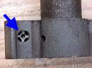
Differential action gives a marginally better ride, although the improvement is marginal. Few vintage car owners are able sense the difference between 60/40 and 50/50 shocks. At any rate, biasing shock action toward rebound, when the springs extend at their natural and predetermined rate, imparts consistency to the process. Nearly any combination of spring deflection and axle velocity can occur upon initial joust.
It should also be remembered that Houdailles are velocity sensitive because of the turbulent flow across the needle-valve restriction. That is, damping increases in some non-linear fashion with the rate of suspension acceleration. A violent upward movement of the suspension will result in a large damping force even though internal check valves snap open. By the same token, the springs are free of parasitic shock-absorber loads during gentle dislocations. Because body roll occurs fairly slowly, the shocks do little to control it.
Notes on Components
- The threaded lock ring permits the reservoir cover to be positioned correctly and tightened against leaks.
- The adjustable needle valve compensates for minor wear and gives the operator some control over ride quality.
- Fluid leaking around the rotor shaft returns to reservoir via a port in the side of the shaft-bearing boss. Consequently, the reservoir seal has little pressure on it.
- The replenishing valve in inner cover opens automatically to top off the associated working chamber.
- Two bleed plugs in inner cover vent air and gas-off from working chambers into the reservoir. These plugs may function as pressure-relief valves.
- X-pattern oil passages in the rotor equalize pressures on both “wings” to reduce bearing wear.
- One or two check valves, usually mounted in the stator, provide differential action.
Nominal Direction of Rotation
Reservoir covers are marked “CW” or “AC” to indicate the direction of rotor rotation that causes the check valves to open. When viewed from the front, as if mounted on the car, the CW rotors turn clockwise during the upward, and less damped, movement of the axle. The same upward axle movement causes AC rotors to turn anti-clockwise.
CW and AC shock bodies and stators do not interchange, although it is not unusual to find the wrong cover installed or the rotor 180° out of phase. The table below should help clarify matters, at least for Model A's.
| Code on Reservoir Cover | Direction Rotor Turns During Joust | Stator/Rotor Check Valve Status | Approx. Pinch Bolt Orientation | Filler Plug Orientation | Shock Installed Location |
| CW | Clockwise | Open for reduced damping | 9 o’clock | 40 deg left of vertical | Right front, left rear |
| AC | Anti-clockwise | Open for reduced damping | 3 o’clock | 40 deg right of vertical | Left front, right rear |