|
|
|
|
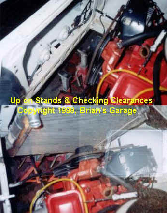
How to Install a Griffin Radiator in the Early ZThis page details how to install a Griffin aluminum radiator into an early Datsun Z. BackgroundMy Z is Chevy V8 powered. I tried the rather large '79 ZX radiator, but it was not quite efficient enough during the summer months (Note that the ZX radiator is physically larger than the Griffin). I contacted Griffin radiator and explained my situation. For my application they suggested a Nascar, 2 row, 1" tube, aluminum that measures 24" wide and 19" tall. I then purchased the radiator, (P/N GRI-125202), from Summit Racing, (1-800-230-3030), for $179.00. After receiving the radiator, I measured everything and 3D modeled it with CAD. I then measured my Z radiator core support and modeled it too. From these files, I designed an attractive, lightweight, rigid, and adjustable mounting system. This system required special tooling to fabricate and I would not expect the average mechanic to do the same. However, the information supplied in this write-up should help get one started and convey what to expect during the installation. Basic Radiator DimensionsThe Griffin does not mount like a Z, or a Chevy. It does not use mounting flanges, nor does it employ a designated supportive area on the tanks. It has C channel rails, top & bottom. The C channel extends past the top and bottom of the tanks about .2-.3". This is where the over all height (OAH) is measured and found to be 18.9". The tanks are actually 18.5" tall. The over all length (OAL) is measured from outside edges of the tanks. This dimension is 24.0". The tanks are wider than the core (2.25") and at the widest point (at the weld) are 3.1" wide. The water inlet is 1.5" on the top left. The water outlet is 1.75" on the bottom right. Note that the outlet has a slight angle towards the the Chevy water pump which takes a little stress off of this fitting. Fit Relative to Z Core SupportThe Griffin fits, but not as well as one would like. When in the proper position (gotta have about 1/2" between the hood and the cap), the lower channel will be hanging down about 2" from the bottom of the lower core support rail. This is measured at the lowest point of the support rail. Or, if measuring from the top of the core support, 1/2" down to the top channel. Note that a radiator utilizing the the slant corner filler will enable you to move the radiator up 1/2" to 1". I think Ron Davis has one like this, but they are more expensive.
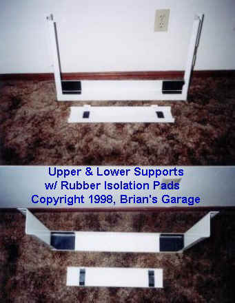
Building The Lower MountThe lower mount should form a C Channel. The radiator tank edges will be located fore and aft off of the C channel sides. The radiator will be suspended on it's lower aluminum channel by the center (web) of the C channel. Since the radiator hangs down below the core support rail, it would be a good idea to make the front side (flange) of the channel at least 2.5" tall to protect from sticks and stones. The other flange need only be about 1.5" tall. The inside dimension between flanges should be a minimum of 3.38". The maximum width of the tanks is 3.12", which leaves you with .25" for some rubber material. You gotta have rubber in between all aluminum to steel contact points. It doesn't take a genius to figure out why. I used .094" thick rubber. You can use whatever is available, i.e. inner-tube rubber. The channel should be 25" long. The distance between frame rails is about 26.5".
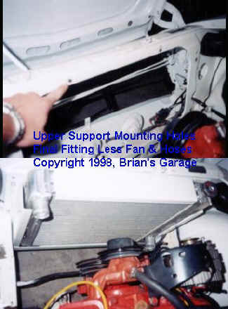
Building The Upper MountThe upper mount is also a C-channel. However, it does not locate the radiator fore and aft using the sides of the tanks. The reason is that there really isn't much room since one tank has a filler cap, and the other has an inlet in the way. Instead, locate off the inside of the radiator upper channel. I bent up an 18 gauge channel, 18.5" long. Flanges were 1.5" tall with 3.38" measured inside between flanges.
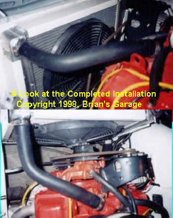
Finishing UpAt this stage we should have our mounts completed and installed, rubber isolation at all contact points, and the radiator sitting pretty. Time to install the tranny cooler, radiator hoses, and electric fan. I'm not going to talk about tranny cooler and fan mounting (those are obvious), but I would like to give a few pointers on finding the right radiator hoses. To find the correct radius of hose, take a length of copper or aluminum tubing and bend it to match the inside radius of the hose you will need. For example, I put one side against the engine thermostat housing and then routed it to the inlet of the Griffin. I tried to use a straight path while allowing for about a 6" radius before the inlet to the Griffin. Do the same thing for the lower hose. Now, go to your local "friendly" Napa store. Ask to see the hose selection (it's normally hung on a wall in the back). Check the label to see what size each end of the hose is (can be different). Lay your piece of tubing against the inside radius until you find a match.
If you can't find a formed hose to fit, try a flex hose. The parts guys will have a book listing hose lengths and diameters of each end of the flex hose. Flex hoses generally wear out sooner and tend to restrict fluid flow. Well, that's it. I hope this may have helped some of you. |
|
Questions or Comments? E-mail me at: [email protected] . Copyright �1996, Brian's Garage. Property of Brian Holdeman, P.E. This page was last edited on 12/28/01. This page hosted by |