|
|
|
|
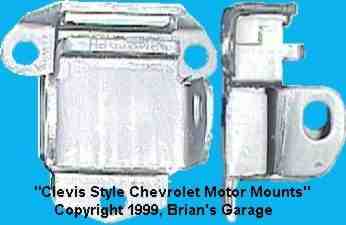
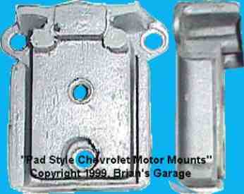
Motor Swap 101, Part IIMounts & DrivelineThis page explains the basics of custom motor and transmission bracket design. It also explains the process of phasing the driveline. If you haven't read Part I, you should do so now in order to get up to speed. What Method?There are two popular methods for mounting an engine to the car. The first uses a rigid bracket between the engine and a rubber isolated mount bolted to the car's structure. Most of the '70's GM cars and trucks use this method. The second is to reverse the sequence, and use brackets from the car structure to cushioned mounts bolted to the engine. Each method has it's place. If the resulting position of your engine (after completing the steps of Part I) has the center of your engine bolt pattern displaced more than 2 or 3 inches relative to the mounting points on the car, use the first method. This is especially important on lightweight cars. This will take the bending stress off of the car's relatively thin and weak structure, and place it on the rigid and strong engine structure. For example, A V8 Z in a "set-back" position will use this method. Racers prefer this position due to it's possible 50/50 weight bias. If your engine bolt pattern is very near the car's mounting points, use the second method. On my SSZ swap, the engine bolt pattern was centered front to back over the Z car's factory motor mount brackets. For this reason, I chose the second method. This "forward" position did not hurt the weight bias as much as one might expect. At curb (wet) weight, my Z has a 52/48 bias. I believe the bias would be at least 1or 2% worse with a lighter transmission than my AOD. But, let's put this bias into perspective. A 90's Trans Am is about 57/43. This forward position required less modification than a "set-back", and made the swap clean, reliable, & very easy to work on . Choosing OEM Mounts (Engine & Transmission)Unless you intend on drag racing, you will need some amount of cushion in your mounts. It is a very bad idea to use solid mounts. They will transmit tons of unwanted vibration and noise. They will also tend to fatigue and break either themselves or what they are attached to. The solution is to use some OEM rubber isolated mounts which are well suited to your idea of how your mounting brackets will look. There are two Chevy styles which are good candidates for motor swapping. Both of these date back to the '60's, will handle a mild Chevy, are inexpensive, and most importantly.... are really easy to adapt to.
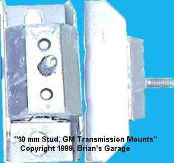
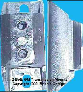
For my SSZ, I chose the clevis style due to it's slotted hole. The slotted hole allows it to work with "I made it with a hacksaw and 110 volt welder" tolerances. Either of these is a good way to go. Use which ever will simplify your design the most. Now it's time to select some OEM transmission mounts. No solid stuff!!!
Designing The Motor Mount BracketsWe have selected our method and our OEM cushion, now it's time to bridge the gap between the OEM mount and the car structure (or engine, depending on your method). First, bolt your OEM mounts onto your engine core or car structure. Roughly measure the gap and offset between the car's brackets (or structure), and the OEM motor mounts. Next, try to visualize these dimensions in shapes of tubing, channel, and angle. It's much easier to build things from structural shapes rather than building each plane independently. Keep in mind that boxed shapes are more rigid than open shapes. Also, think about the direction of forces due to engine torque, engine weight, and acceleration/deceleration of the car. You will need to counter these forces by putting the right amount of steel in the right place. Now that the basic look of the mount has been determined, try modeling the concept with whatever. Build your model right on the car. You can use poster board, modeling clay, wood, aluminum foil, tubing... just about anything you like. Don't forget to allow access to mounting bolts. Now that you have a model, break out the hacksaw, welder, and grinder and make the real thing. If it's not quite right the first time, that's o.k. Even as simple as my mounts were, I made them twice. Materials used in building the mounts should be of reasonable thickness. For example, if the factory mounting bracket is 1/8" thick, do not bolt a piece of 1/2" plate to it and expect it to live. The general rule of thumb is a max of 2-3 times the thickness of the adjoining part. This will normally keep you from cracking things up. If you must bolt thick to thin, use a load distributing plate between the nut or bolt head and the thinner piece of steel. Yes, this is the same thing as a large washer.... Avoid welds in areas of high stress. Welds make metal weak... period. It's not the weld itself, but around the edges of the weld (toe & root). This area is very susceptible to crack formation.
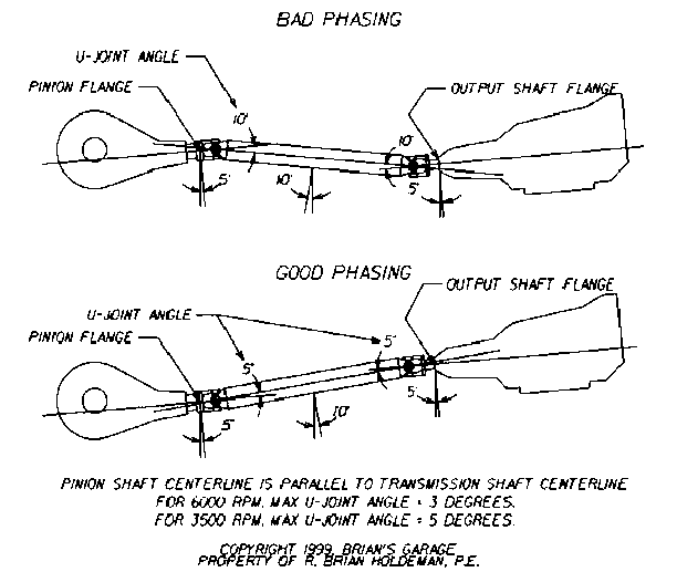
Phasing The DrivelineHaving completed the motor mount brackets, it is time to phase the engine and tranny to the pinion shaft of the differential. You cannot skip this part. If you do, you'll be lunching u-joints, bearings, and seals. You will also be subject to enough vibration to rattle your teeth loose. The basic idea is to make the tranny shaft centerline parallel to the pinion shaft centerline. This parallelism is measured using an "angle finder" (can buy this at Sears). When the upward angle of the differential equals the downward angle of the transmission, they are parallel. Begin by laying the flat side of the finder against a machined surface at the pinion. In the case of my 240-Z, this was a flange. Other cars (Chevy, Ford, etc.), have a yoke. Record this pinion shaft angle. Typically, this angle is anywhere between 2 and 7 degrees up. My 240-Z showed 5 degrees. Next, place the angle finder against the output shaft, or seal flange of the transmission. Raise or lower the transmission with a jack until the angle is the same as the recorded pinion shaft angle. In the case of my 240-Z, this was 5 degrees down.
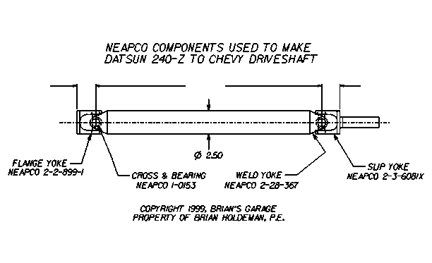
If there is an obvious angle problem as described above, it may be a good idea to mock up a driveshaft and use this to measure true U-joint angle. I took the rear half of the Z shaft and mated this to a Chevy shaft. To do this, I had to lathe a bushing to fit the I.D. of the Z shaft and the O.D. of the Chevy. The tolerances were such that there was just barely a slip fit. Take the shaft assembly and install it. After the back half of the shaft is secured to the pinion flange or yoke, slide the front slip yoke into the tranny until it bottoms out. From this point, back it out 1/2"-3/4". This 1/2"-3/4" of clearance is necessary to accommodate the front to back movement of the solid axle assembly as the car's suspension goes through it's motion. This front to back movement does not happen on an independent axle as on a Z or Corvette. The differential is bolted to the car and not to the suspension. Even so, you'll need to have at least 1/2" clearance in order to install the shaft over the pinion flange or yoke saddle. Now it's time to tune in the ideal U-joint angle. Place the angle finder against the shaft. The measurement will have to be added to or subtracted from the angle of the pinion flange and shaft seal flange (see phase drawing). Here's something else they never tell you in the magazines. The Chevy intake manifold carburetor pad has about a 3 degree angle built in. This is to accommodate the angle of the engine and transmission. It is important to try to keep a Chevy engine and tranny combo close to this angle if you want your Quadrajet carburetor float to work correctly. This angle also helps the engine and transmission fluids flow as Chevy intended. In the case of my 240-Z, I needed to raise the tail of the tranny and drop the nose of differential. Raising or dropping the tranny tail is not a problem since a custom tranny crossmember. will be made soon. Unfortunately, raising or lowering the nose of differential. will require some extra work. On a car with a solid axle and leaf springs, this is done by simply adding wedges between the axle mount and the leaf spring. On a solid axle with four link, either the links will need to change length or their attachment points moved (major bummer!). On an independent axle, the front or rear differential mount will need to be modified. I ended up making my own front differential mount for my Z. This was made from a piece of 3/8" bar, a steel sleeve, Grade 8 fine thread C'sink bolt, and two pieces of 3/8" 80 D urethane material to dampen out vibrations. As I said before, mounts should not be solid on a daily driven car. I finally ended up with a U-joint angle of 2.5 degrees at the differential and 3 degrees at the tranny. This resulted in a U-joint angle of about 2 degrees. Try and get that with a 240-Z employing the "set-back" approach!
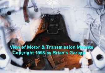
Designing The Transmission CrossmemberNow that we have the approximate final resting place of the transmission, it is time to build a crossmember. around it. First, determine if you will be using the factory mounting locations, or a new location all together. Here, as on the motor mounts, try and use factory mounting locations if possible. If you read part one, you'll know that I had to remove the spot welded Datsun transmission mounting brackets from my car. When I did this, I was careful not to screw them up. I ground, straightened, and reformed the flanges. Then I bolted these to my custom crossmember. The crossmember was then bolted to the transmission (transmission still in phase as described in previous section). It was quite easy to see what modifications had to be made to the factory brackets in order to reweld them to this new location in the transmission tunnel (see picture "View of Motor & Transmission Mounts"). Try and model the crossmember with wire, tubing, card, etc. to get the basic shape. If necessary, add "humps" for exhaust pipe clearance. Again, try to think in terms of tubing, channel, etc. On my SSZ, the mounting points were less than 12 inches apart. For this reason, I was able to make the crossmember from a single piece of 7 gauge by 2-1/2" strap. This is a very strong and lightweight design. I included clearance for the exhaust. It bolted up very nicely to the factory mounting brackets. Normally, a transmission mounting plate is welded to the crossmember. It should have holes slotted front to back for ease of installation. More to come...... |
|
Questions or Comments? E-mail me at: [email protected] . Copyright �1996, Brian's Garage. Property of Brian Holdeman, P.E. This page was last edited on 12/28/01. This page hosted by |