 TO
TO 
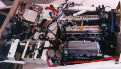
Wiring, Wiring and more damn wiring.
To connect THIS TO
Wiring the body harness
Well this section of the build is dominated by one task, wiring. I probably could have saved a lot of time and spent the $300 or $400 but that would mean that I didn’t "learn" the fine art of being an auto-electrician J . But in all seriousness if you have an option of buying a pre-made wiring loom – DON’T. The task is frustrating but you have a series of personal wins every time a new circuit works. My wife hated it every time I called out to tell her:
Ask her some time how many circuits there are in a car!!
So how did I proceed?
As indicated earlier I extracted the wiring loom from a 1975 Triumph 2500PI. This car has no special attributes for the donation other than it was handy and I used the Smiths gauges from this car.
I then spent about 2 hours cutting all the tape from the wires so I had all the wires laid out on the concrete driveway. Then following the wiring diagram for the Triumph I extracted the wires one circuit at a time.
At first I was confused about the ignition switch. As soon a s I realised in my (peanut-sized) brain that the ignition switch is nothing more than a power source I was right to go. I simply connected the battery up to one side of the fuse box and went for it a circuit at a time.
It took about 6 hours to get the first circuit working and then about 4 days to finish the body harness and get it taped up in place. I also used the major connecting blocks from the Triumph, but I cut all the other connectors off and used new connectors so that the job had a nice clean uniform look.
To complete the body harness "task" I plan on scanning in the Triumph wiring diagram, then using a bit-map editor, edit out the unused circuits and add in the new ones (fuel pump and thermo-fan). Ill add this onto my page as soon as I get the chance to scan it in!
The next job is the ECU – Well that looks complex – but flushed with success from my body harness task I think Ill have the confidence to bowl this one over.
The Handbrake Take 2
Well as luck would have it my next door neighbour bought an ARC welder! – Yeehar!
So I set about and made a few brackets to attach a pair of handbrake cables to each rear wheel, out of 3mm strap steel. Well, I am not going to describe the process in too much detail – cos it failed. The handbrake work well on the flat, but when I pushed it out onto my moderately sloped drive way – It rolled back into the garage!! I tried to adjust the slack out of it and – frankly my design was shitty!!!
So back to the drawing board.
Look out for The Handbrake take 3!
(This reminds me I haven’t paid the guy for the cables yet – oops better get a cheque in the mail today!!)
The ECU
Wiring up the ECU has been a task Ive been dreading from the day I started building the car. Simply a fear of the unknown. So I borrowed a couple of excellent books "EFI and Engine Management Volume2" and "Max Ellerys Corolla Workshop Manual". These two texts gave me enough courage top tackle the task. Once I started Ive discovered that I have a 100kW engine and an 86kW computer!! Hmmm this sounds like trouble to me - but after some discussion with Toyota in Canberra they assure me that the differences will not be insurmaountable and its is only a case of me mapping one wiring diagram to another!?! Well this was undertaken and with the exception of a few "missing" wires in the ECU I think the thing will go (as at the date Ive written this I have still not started the engine!) But all the wires have now been connected - All I am waiting on now is the exhaust so I can safely start it without burning the bodywork. The wiring left to be done at this stage is to test the ECU, to install the fuel pump and the fuel pump relay, hook up the ignition switch and tie down all the wiring harness to the body with clips.
Next Page - The Move to Melbourne