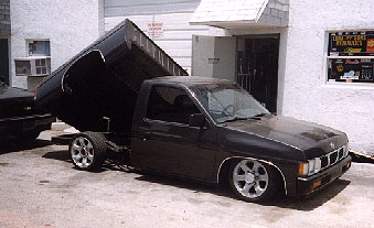
 picture 1 |
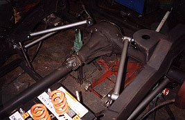
Stock rear frame with all factory components removed ie: springs, brackets ect. |
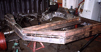
| First section of tilt bed. Frame support and bottom hinge of tilt with excess frame to be cut off. New frame support made from 2x3 box tube cut and bent at a 35 degree angle. |
 picture 2 |
 picture 3 |
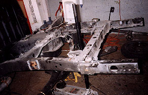
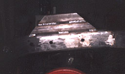
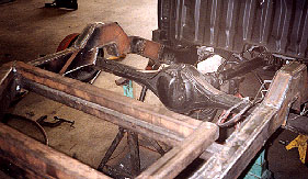
Bottom hinge made from 1" inner diameter pipe welded to bottom frame. |
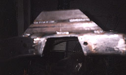
| Upper frame made from 2"x2"x1/4" box tubing and upper hinge made from 1" inner diameter pipe and welded opposite to the top of the frame. | 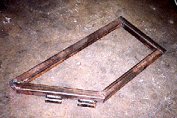 picture 4 |
 picture 5 |
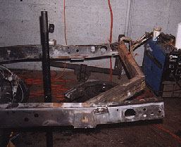
Both pieces are then placed together and a 1" diameter solid rod is used for the center pin of hinge. |
| Inside view of upper rack and hinge assembly. | 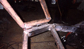 picture 6 |
 picture 7 |
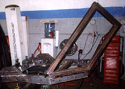
The 35 degree frame support will produce a 90 degree diamond tilt when completed. |
| An 8" reds hydraulic cylinder was used to provide the full extension of the tilt bed. | 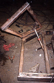 picture 8 |
 picture 9 |
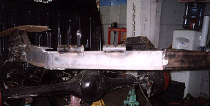
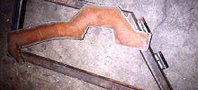
First stage of a super c-notch. 2"x2" box tubing is used as frame support before the notch is cut. |
| Super c-notch is cut from old section of frame. Notice only 1/4" of original frame is left, without reinforcement frame would fall apart. |
 picture 10 |
 picture 11 |
A 1/4" steel plate was made for reinforcement of the frame and super c-notch. |
| After 1/4" plate is welded to the frame all the welds are ground down for a nice smooth look. | 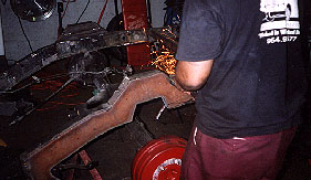 picture 12 |
 picture 13 |
With the frame work completed and boxed off we are ready to begin the 4-link. |
| First step in making a 4-link, The wheel base must be measured from stock suspension so that the completed 4-link will retain the same wheel base. Front hangers for bottom links are made. |
 picture 14 |
 picture 15 |
All brackets are made from 3/16" steel. |
| Diagnal 4-link kit consists of 2 upper links and 2 bottom links made from 1" inner diameter pipe. |  picture 16 |
 picture 17 |
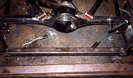
To keep original wheel base, bottom link is measured from fabricated front hanger to center of axel to determine overall length of link. |
| With bottom link in place the rear brackets are tacked to the rear axel. |  picture 18 |
 picture 19 |
The upper links determine pinion angle, adjustment is made with bottom links in place. First pinion angle is determined then the upper diagnal link brackets are tacked into place. |
| Once all the brackets are tacked into place a final test fit of the 4-links can be done to check pinion angle and side to side sway motion. Once done final welding can be completed. |
 picture 20 |
 picture 21 |
Upper rear cylinder bracket welded into place. |
| Battery trays are made to house 4 deep cycle 31 series batteries. |  picture 22 |
 picture 23 |
The pump rack was made to fit behind the axel and hold 3 pumps, 2 for the suspension and 1 for the tilt bed. |
| After all welding is done the frame is ground down again to make the frame as smooth as possible. | 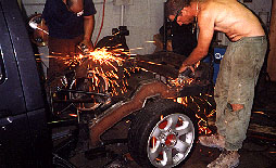 picture 24 |
 picture 25 |
The frame is then prepped and painted to prevent rusting and provide a show quality finished product. |
| The tilt bed pump tank had to be cut 2.5" to clear the rear axel. | 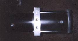 picture 26 |
 picture 27 |
All pumps are then mounted plumbed and wired up. |
| A plate was made inside the bed to match the upper frame hinge to bolt the bed to, the 2 long aluminum pieces are to hold down the fuel cell to be added later. |  picture 28 |
 picture 29 |
Fuel cell is then bolted to the bed floor and the stock fuel pump and sending unit are used. |
| Job completed!, A 90 degree diamond tilt and a frame layin 4-link is ready to go! |  picture 30 |
� 1997 [email protected]