ELECTRO MAGNETS
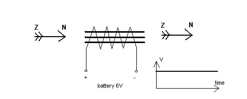
Simply put, if you have a current flowing through a conducting wire, then you can find a magnetic field around that wire. In the picture you see how a DC current (constant voltage in the Voltage-time diagram) through the coil, directs the compass needles. The more current, the stronger the field. You can bundle all that magnetism by wrapping a long wire around an iron core. That way you can make very strong electro-magnets.
Another phenomenon, is when you have a changing magnetic field near a conducting wire. That changing field causes an also changing voltage at the wire-ends. Of course the effect is again greater if the wire is wrapped around an iron core. The picture shows how a rotating magnet gives an AC voltage.

These two effects are for example used in a transformer, that transforms the household 220 Volt AC to, for example, 22 Volt AC. The voltage at the primairy coil causes a current flowing through it. Because it is an alternating voltage, the current is running up and down the wire, changing direction 50 times per second. That current gives a magnetic field in that coil. Because the second coil is on the same iron core, that same magnetic field will be there too. And because it is a changing current, it is a changing magnetic field, so a voltage on the terminals of the second coil is the result.
Now the funny thing, the ratio of the primary and secundairy voltage is the same as the ratio of the number of windings of the primary and the secundairy coil. So 1000 windings on the first, and 100 windings of the second give a transformation from 220 to 22 Volt. The same principle is used in the ignition coil, although here it is the other way round, a small voltage change transforms to a high voltage change. The winding ratio is about 1:100 in an ignition coil, so in a 6 Volt system you would expect a high tension voltage of 600 Volt. That is not nearly enough to get a spark. You need between 10 and 20 kiloVolt for a nice reliable spark.
Here another effect is important, the selfinduction of the coil. Because a coil also reacts to its own magnetic field, it tries to resist any change in current.
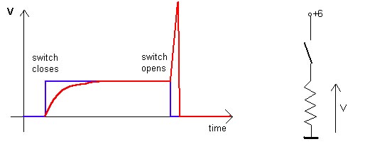
In the picture the behaviour of the points is the blue line, while the reaction of the voltage over the coil is the red line. When the contact points are closing, the current won't start to flow immediately at full strength, but opposed by the selfinduction will only gradually increase. As a result also the voltage will only gradualy increase. When the points open, the current is suddenly cut off, and the coil protests loudly. The voltage doesn't drop to zero, but an opposing voltage peak up to 200 Volt is the result. This voltage peak, transformed up 100 times gives the neccesary 20 kVolt at the sparkplug.