| MS-6905 meets the
Tualeron Mod
| By:
Haut^Karl |
Saturday,
November 30, 2002 |
It would be difficult to apply
the right mod if you didn't know what version
of MS-6905 you had. With the help of our friend
N. Yagi and his article in Japanese, here,
we were able to bring you the following chart
and pictures to identify your MSI slotket. There
may be more versions of the 6905, but this chart
lists the major changes we/N.Yagi know about.
We worked out a mod for the MS-6905
1.1 Rev. A which "should" work on
all of the non-'Master' versions. The 'Master'
versions were properly designed to support Pentium3
CPUs and they accept the typical 3-pin mod.
The Rev. B slotket is a big question mark as
it was supposed to support Pentium3 CPUs but
was recalled
because it didn't work properly. Have to wait
for a user to try the mod on a Rev. B slotket.
Table 1
Model |
Description |
Picture |
MS-6905 1.0 |
Celeron-Only operation(66
FSB). No jumper for 100 FSB/B21 or jumpers
for VID selection. Silk screen for jumper
shows up in later copies of this model.
|
Picture |
MS-6905 1.1 Dual |
Added jumpers for VID
1.8-2.4v and Dual-Proc selection. No jumper
for FSB 100/B21 operation. |
Picture |
MS-6905 1.1 Dual (Rev.
A) |
Added jumper for Dual-Proc
operation. Adapter was manufactured to
be stable at FSB 133. Some Rev. A adapters
came without J2 soldered in. |
Picture
|
MS-6905 1.1 Dual (Rev.
B) |
Added J4 for FSB 133
selection and plastic retention mechanism.
Intended to support Pentium3. Was recalled
by MSI since Pentium3 support was flawed. |
No Pic |
MS-6905 Master 2.0 &
2.3 |
Added TVC chip and plastic
retention mechanism, J4 for FSB 133, support
for Coppermine 256k. Ver 2.0 has 3 pin
J3 and Ver 2.3 has 4 pin J3. |
2.0
2.3 |
Picture
1

Picture
2

All right. Grab
a drink and head for your workbench. This mod
is a little more involved than the Generic
Slocket Mod.
Diagram
1
Step 1: Open
your ZIF socket
Remove the sliding part of the
ZIF socket with a small screw driver(Refer to
this article
for help). Use a black pen and blacken-in the
two indexed corners so you don't get the pins
mixed up. Mark the following pins on the ZIF
socket with black: AN3, AM2, AG1, AK4, AJ3,
X4 and Y33. Be careful since the pin numbers
are reversed when looking down on the socket
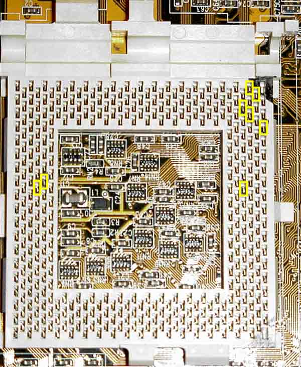
like in the picture below. If you look at the
back of the slotket(Picture 2),
the pins of the ZIF *now* correspond to the
pin numbering in the Intel pdfs. We are going
to use sticky tape to insulate these pins.
Picture 3
Use your judgement to figure
out how big the piece of sticky tape needs to
be to cover the contact for each pin. Don't
worry if the tape is too long. You can trim
it down with a sharp razor blade. After you
insulate all 7 pins, you can reassemble the
ZIF socket.
Step 2:
Building Bridges
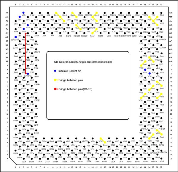
Check the following
ZIF socket pins with a voltmeter for connectivity
to Vss or Vcc(just in case other revisions of
the MS-6905 are different to the Rev. 1.1a adapters):
AN11, AN15, AN21, AL13, AL21, AK16, AH20, AA33,
AA35, U35, U37, S33, S37, G35, G37, E23. If
these pins are not connected at all, we need
to bridge Vcc to them(Vtt would be better, but
we have to generate the Vtt 1.25v ourselves
which is a mod we plan to do in the future).
For our MS-6905 adapter we had to connect(refer
to yellow in Picture 2) all
of the above pins to nearby Vcc pins. AN15 should
be left alone if you want to attempt to use
this in a dual processor setup.
Check for a connection
between AH4 and X4 as this re-routes the RESET
signal to the old location. For the Rev. 1.1a
adapter, we soldered a thin wire from AH4 to
X4(see Picture 2).
Note:
For the adventurous overclocker, you can power
the Vtt pins using a 1.5v source. We didn't
get around to doing this extra step since the
adapter belonged to a friend and is no longer
in our possession. After you finish the normal
steps, measure pin AD36 for 1.5v while you have
Vcc set to something other than 1.5v just to
make sure AD36 is not just another Vcc pin.
It shouldn't be. Then follow along here
.
Step 3: VID
settings
Did you know that the MS-6905
series of adapters are capable of voltage settings
from 1.3v to 3.5v? Of course your motherboard's
voltage regulators must be capable of producing
the voltage you select. Read more.
Before we knew the MS-6905 had
VID settings down to 1.3v using the jumpers,
we did the manual VID mod(Moved and expanded
on, here).
Step 4:
CPU Bridges
Diagram
2
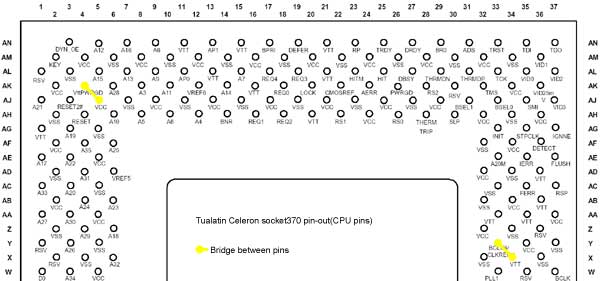
Grab your conductive
paint and make the bridge from AK4 to AJ5(Check
this article
for optional AK4 bridges).
Finishing
Step: Installation
Insert your Tualatin
processor into your slotket, remove the thermal
pad & adhesive from the heatsink, apply
some thermal grease, and install your heatsink.
Set jumpers J1=bridged, J3=No Bridge, J2=2-3.
Plug the slotket into your motherboard, clear
the CMOS, then power-up. Are we booting?
Troubleshooting:
If you need some help from fellow
modders, try any of the forums below.
The LunchBox Forums
Forum Thread at Overclockers.com:
"running
Tualatin on CuMine MB w/o Powerleap"
Forum Thread at MadOnion.com:
"Tualatin
on a BX Mobo works. No Adaptor Required"
|
