Enhanced Low-Magnification PLM Examination
of Asbestos-Containing Materials
Employing a Simple Microscope Modification
to Achieve Dispersion Staining
June, 2000
Michael A. Gorycki, Ph.D.
ABSTRACT
The use of a low-magnification (4X) objective in polarized light microscopy (PLM) to estimate the percentage composition of various constituents in asbestos-containing building materials (ACM) is recommended. It is employed with various combinations of routinely-used optical accessories to enhance or suppress sample components. These accessories also include an easily constructed field lens central stop which produces peripheral illumination, generating darkfield conditions, and instantly permits low-magnification dispersion staining observations with that objective. The use of the field lens central stop, combined with heated slides to enhance visualization of fiberglass and similar materials, is also described to improve the estimation of their percentages on a slide. A table is provided listing some common ACM and the appropriate optical setup, using routinely-employed high-dispersion 1.550 R.I. immersion oil, for the best observations of chrysotile asbestos and quantification of associated building material components. A simple field lens annular stop is also described. The technique is also useful in the analysis of mineral fragments and the forensic examination of unknown fibers and particulates.
INTRODUCTION
Use of a low-magnification (4X) objective in the polarized light microscopy (PLM) examination of prepared slides of friable, asbestos-containing building materials (ACM) has the advantage of a large field of view (5mm diameter) and is recommended for the estimation of percentage compositions. This is particularly true if the constituents of a sample are not uniformly distributed across the slide or if some components are large or elongate and tend to extend beyond the field of view of a higher-magnification objective. As will be shown here, the optical setup of the microscope as the 4X objective is employed can be easily modified in various ways to enhance the examination of common ACM. Since chrysotile is the most common asbestos mineral in ACM, and high-dispersion immersion oil with a refractive index of 1.550 is the oil most commonly used, this paper describes the observation of chrysotile and a number of common materials in slides prepped with that oil. However, other asbestos minerals in their appropriate immersion oil and associated building material components can be accommodated with this technique.
It should be noted that the methods described here are not meant to supplant any portion of EPA (1), NY State Department of Health (2) or other recognized methods of PLM analysis (3). They are, rather, to be considered a logical supplement to the systematic order of examination of bulk samples which include: visual (1X), stereo microscopy (10X-150X), and PLM (100X-400X)(4). This investigator routinely uses an Olympus polarizing microscope with 10X, 20X and 40X objectives in addition to an Olympus E A4X, 0.10 N.A. objective.
Following are the optimum optical conditions suggested for the enhanced analyses of a number of common ACM in 1.550 R.I. oil. Most include use of a field lens central stop (FLCS), which will be described below; some require heating of specimen slides. A condensation of the various materials and optical setup for analysis is given in Table 1.
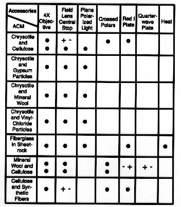
(Table 1. Table of building materials and optimum low-magnification optical configuration for PLM bulk analysis using 1.550 R.I. immersion oil.)
Chrysotile and Cellulose
The combination of small amounts of chrysotile and large amounts of cellulose fibers, as in bulk samples of air cell, can be very difficult to analyze because of a general similarity of both fiber types. To facilitate viewing chrysotile using a high dispersion immersion oil with a refractive index of 1.550, all that is required is to construct a FLCS composed of a U.S. cent glued to the center of a glass slide. This FLCS is centered over and rests on the well of the field lens of the microscope (Figure 1) and produces a darkfield condition if the 4X objective is used. It is reminiscent of a Rheinberg filter; the stop produces a darkfield, and the periphery of the field lens illuminates the object. The condenser is racked up close to the slide being examined and maximum illumination is employed. Precise centering of the FLCS is not critical, requiring only a casual inspection of the field of view as the FLCS is moved. Other microscopes may require a similar FLCS, possibly with larger or smaller diameters. However, the same FLCS has been used with an Olympus MDPlan 5X objective, and also with a Nikon polarizing microscope with a Nikon Plan 2X, 0.05 N.A. objective, with similar results and an even larger field of view (9mm).
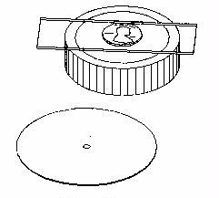
(Figure 1. Sketch of the field lens central stop (FLCS) composed of a U.S. cent glued to a microscope slide. The slide rests centered on the well of the field lens and produces dispersion staining on a darkfield when the 4X objective is in use with plane polarized light. A 5cm diameter opaque plate (jar lid) with a 2mm central hole is also shown. When centered on the well, it produces field lens annular stop (FLAS) dispersion colors with the 4X objective.)
In use, the FLCS generates hollow cones of light, one beneath the condenser and one above the sample. Since the upper cone's diameter is greater than the first lens of the in-focus 4X objective lens (Figure 2), a darkfield-like condition obtains, but any dispersion colors produced by the sample will enter that objective and become visible. Use of the FLCS, 4X objective and plane polarized light, quickly and simply convert the 4x objective to a dispersion staining objective which allows for a rapid search of the entire slide to detect the red-purple and blue dispersion staining colors typical of chrysotile. This is a remarkably proficient use of the low-magnification dispersion staining configuration. On numerous occasions, small bundles of chrysotile within masses of cellulose fibers could be readily detected in this fashion. At higher magnification (100X) and with fine focussing, these chrysotile bundles could be recognized only with great difficulty even while knowing of the presence of the chrysotile directly under the crosshairs!
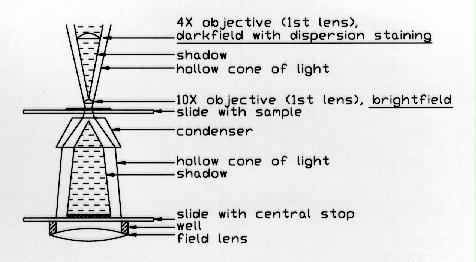
(Figure. 2. Cross-section of optical system to produce dispersion staining using a 4X objective and the FLCS resting on the microscope well. Rays shown are approximate. Note positions of first lens of in-focus 4X and 10X objectives relative to the hollow and solid cones of light above the specimen.)
As previously described, an added convenience to using the 4X objective is that it has a greater depth of field than the 10X objective, does not require constant focusing and reduces the chance of missing an out-of-focus bundle of chrysotile. Morphologic confirmation at higher magnification only requires rotating a 10X (or stronger) objective into position and inserting the analyzer and Red I plate to produce typical brightfield conditions. The FLCS may be left in place when the 10X (or stronger) objective is employed because brightfield illumination obtains since the first lens of the in-focus objective enters the cone of light below the hollow portion (see Figure 2). The FLCS, however, should be removed if the upper condensing lens is employed with higher magnification objectives.
To quantify high percentages of chrysotile, use of the Red I plate, crossed polars, and 4X objective causes the chrysotile to be as bright as the cellulose (Figure 3). Adding the FLCS causes the chrysotile, against the darkfield background, to be much less bright than the cellulose which has better definition (owing to its ultrastructure), compared to the chrysotile. (Figure 4). Moving the FLCS out and in (Figures 3 and 4, respectively), may permit the best estimate of cellulose versus chrysotile, based on their relative definitions, when these two components are intimately mixed on a slide.
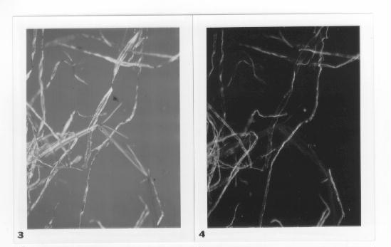
(Fig. 3. Cellulose and chrysotile fibers intimately mixed. 4x objective and Red I plate are in place. Note that the kinked chrysotile bundle in the center of the figure is comparable in brightness with the cellulose in this micrograph. 40X. In this and other micrographs, refer to Table 1 for optical configuration of PLM to maximize visualization of slide components.
Fig. 4. Same as Figure 3, but with the FLCS in place. Note that the kinked chrysotile bundle is barely visible. 40X.)
Relatively small bundles of chrysotile among cellulose, gypsum particles, mineral wool, and vinyl-chloride particles in sheetrock and ceiling and floor tiles can easily be located using the 4X objective, FLCS and plane polarized light (see Table 1). If slides appear negative with the 4X objective, analysis at a higher magnification, including use of the 10X dispersion staining objective employing both central and annular stops, must be used to confirm the presence or absence of very small asbestos structures.
It should be mentioned that dispersion staining methods become less useful if the immersion oil is contaminated with asphalt or finely dispersed gypsum mortar, but this is also true of dispersion staining objectives at higher magnifications. In these situations, it is best to remove these obscuring materials with heat and/or acid treatment. This, however, would entail quantification involving weight determinations of sample and residue as required for non-friable organically-bound (NOB) samples (2).
Fiberglass in Sheetrock
Fiberglass (and similar materials) in sheetrock can be difficult to distinguish because of masking by the fine-grained plaster mortar. There is also the problem of the refractive index of the fiberglass usually being either close to, or matching, that of immersion oil with a refractive index of 1.550. The first of these difficulties can be reduced by preparing thinner slide mounts. However, using a 10X (or stronger) objective, fiberglass is still difficult to distinguish in these preparations, and it is even more difficult to estimate its percentage because of the need to constantly fine-focus to detect the fibers. Also, because of their length, they usually extend well beyond the field of view. Unfortunately, using a 4X objective to try to facilitate quantification, one finds that fiberglass, in general, becomes virtually invisible and focussing has little or no effect.
Employing oblique illumination with the 4X objective is also of little use if the refractive index of the fiberglass matches that of the oil. Even if the indices are slightly different and the fibers can be made visible with oblique illumination there is a problem in that the fiber lengths are randomly oriented to the shadow's edge. Those parallel to it are highly visible and become progressively less visible until those which are perpendicular to the edge are practically invisible. Added to this difficulty is the masking by the mortar surround. By drastically closing the condenser diaphragm, fiberglass may be made visible to some extent, but this also involves the loss of a uniform, bright field of view.
Fiberglass which has a refractive index slightly different from that of the oil is made visible in any orientation by employing the FLCS because of the peripheral illumination which it generates. This is a radially symmetrical version of oblique illumination. If, however, the refractive index of the fiberglass closely matches that of the oil, the fibers are invisible (Figure 5). However, gently heating the slide for ten seconds on a 50°C hot plate will create a large difference between the refractive indices of the oil and fiberglass (due especially to the change in the oil(5)) and will make the fiberglass markedly visible, regardless of orientation, even if masked by the gypsum mortar (Figure 6). If crossed polars and the 1/4 wave plate are used, upon cooling, the fiberglass rods, which have bright yellow edges, change to orange, then red, and eventually dim to invisibility. Obviously, this technique is the reverse of the often-used method of heating a slide to cause the refractive index of the oil to match that of the object.
Use of crossed polars, the FLCS, and the Red I plate with heated slides causes the fiberglass rods to have bright red outlines against a darkfield background. The fibers are also quite visible if only plane polarized light is used. Again, upon cooling, the edges dim to invisibility. Regardless of the optical setup, fiberglass on heated slides is not visible if the FLCS is not employed. Interestingly, use of crossed polars with the FLCS alone does not allow heated slides to exhibit fibers. The result of this simple and fast method using a single preparation is the easy quantification of the lengthy fiberglass rods at low magnification using an oil with a refractive index of 1.550. Also, there is a greater depth of field using the 4X objective which brings the entire specimen thickness in focus and obviates the necessity to fine-focus to detect the fiberglass.
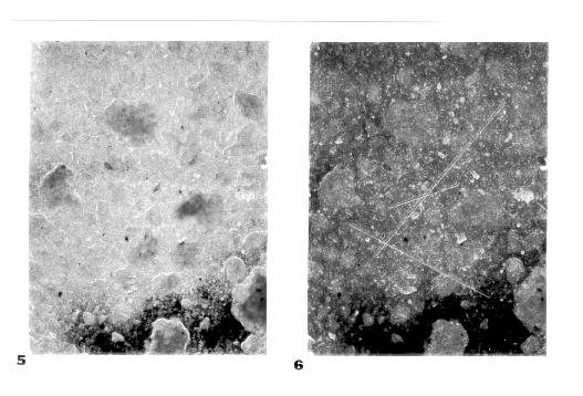
(Fig. 5. Unheated slide of sheetrock bulk sample showing fine-grained gypsum mortar only. Fiberglass is not visible due to masking by the mortar and close match of the refractive index of the immersion oil (1.550) to that of the fiberglass. FCLS and plane polarized light or polarized light with 1/4 wave or Red 1 plate in place. 40X.
Fig. 6. Same as Figure 5, but slide gently heated. The temporary difference in refractive indices between oil and fiberglass allows the fiberglass to be made quite visible to allow for more accurate (usually greater) quantification. 40X.)
Usually, with heating, a great deal more fiberglass is seen than is determined by routine methods (unless other oils are used). The effects of heating are transitory; the slide cools and returns to its original state in about two minutes allowing further examination under otherwise unchanged conditions. This procedure can be repeated with the same slide a number of times and is also useful for samples of fiberglass mixed with mineral wool or other materials (see Table 1). It should be noted that the closer the oil matches the refractive index of the fiberglass or the thinner the fiberglass, the warmer the slide should be to make the fiberglass decidedly visible.
Mineral Wool and Cellulose
If mineral wool, mixed with cellulose, as in ceiling tiles, is examined using the 1/4 wave plate, crossed polars and the 4X objective, the cellulose is more apparent than the wool, but both are not very conspicuous. Mineral wool becomes markedly visible particularly with regard to the thinner fibers if the FLCS is added to the system, but the cellulose tends to disappear (Figure 7). Because of the peripheral illumination, the mineral wool appears with bright yellow outlines against a darkfield background when compared to a brightfield image. Using only crossed Polars with the FLCS will cause the cellulose to remain bright and the mineral wool to become virtually invisible (Figure 8). Moving the 1/4 wave plate in and out, therefore, allows for a good quantification of these two materials. Use of the FLCS (see Table 1) should result in a better (usually greater) estimation of the percentage of mineral wool in bulk samples. This optical configuration is especially helpful if the immersion oil happens to be contaminated with asphalt adhesive and the mineral wool is very difficult to detect (see Table 1). If, instead, the Red I plate is employed, the mineral wool has dark centers (especially the thicker fibers) and bright red outlines against a darkfield background. At the same time, the cellulose fibers will be brightly birefringent, exhibiting various colors against the darkfield background.
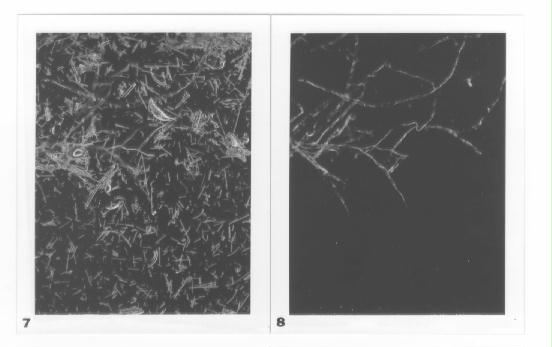
(Fig. 7. Mixture of mineral wool and cellulose with crossed polars and 1/4 wave plate, and FLCS in place. The mineral wool is very apparent, but the cellulose is difficult to see. 40X.
Fig. 8. Same as Figure 7, but with 1/4 wave plate removed. Note that the brightly birefringent cellulose is enhanced and the mineral wool is not at all apparent. 40X.)
Cellulose and Synthetic Fibers
Commonly, cellulose and synthetic fibers can be found mixed on the same slide. If these fibers are unstained, both can have similar contrast under crossed polars (as with chrysotile and cellulose, see Figure 3). Using the FLCS, the 4X objective, crossed polars, and the Red I plate, unstained cellulose fibers appear less visible than synthetic fibers (as with chrysotile and cellulose, see Figure 4). Many synthetic fibers have dark centers and bright outlines while the cellulose fibers are more or less uniformly dim. Repeatedly removing and inserting the FLCS causes the cellulose fibers to become respectively more and less visible thereby making quantification of both types of fibers easier and accurate at low magnification. Since there is great variability in the types of cellulose and synthetic fibers, the usefulness of the procedure described here varies greatly and may require other optical configurations.
A Field Lens Annular Stop
It should be mentioned that a functioning field lens annular stop (FLAS) can be produced by similarly placing an opaque plate with a 2mm hole in its center on the field lens well (see Figure 1). The FLAS (with 4X objective) produces colors complementary to those produced by the FLCS. As confirmation of this, if optical glass test grains with a 1.550 refractive index are mounted in 1.550 high dispersion immersion oil and examined with the FLAS, a reddish Becke line will enter a grain and a bluish Becke line will exit as the objective is raised. However, if the FLCS with the 4X objective is employed, the red Becke line will exit the grain and the blue line will enter as the objective is raised.
CONCLUSIONS
While this discussion has been limited to a few building material components, chrysotile, and use of the FLCS and 1.550 high dispersion index oil, the technique can be used with other immersion oils for bulk sample materials which contain other types of asbestos. The 4X objective and the FLCS have proven very useful in this laboratory but only as an adjunct to higher-magnification objectives and standard methods of testing for asbestos in friable building materials. Again, the technique is also useful in the analysis of powdered minerals and the forensic of unknown fibers and particulates.
While seeing less and less of more and more, the 4X objective complements the higher magnification objectives (where one sees more and more of less and less), especially if detection, rather than confirmation are the goal. It may be possible to use a slightly stronger objective, stronger oculars and, when present, a stronger intermediate lens to increase the total magnification and still obtain low-magnification dispersion staining. By utilizing the various combinations of optical components (including heated slides) described here for low-magnification analysis, the proportion of one or more non-asbestos constituent might be shown to be greater than otherwise determined. Obviously, this would have an effect on the estimated percentage of asbestos in the sample. Also, use of the FLCS, FLAS, and heat dramatically increase the various permutations and combinations of available optical accessories in PLM useful in the examination of a variety of ACM materials. If a 4X objective is already available in a laboratory, the implementation of the field lens central stop should lead to better and faster PLM analyses. For the cost of conversion, it's worth a try!
If you have any questions, or comments, please send email to: [email protected].
You are visitor number:
REFERENCES
1. "Asbestos (bulk) by Polarized Light Microscopy (PLM)" - Method 9002- NIOSH Manual of Analytical Methods, 4th Ed. U.S. Department of HHS, NIOSH Publ. 94-113, 1994 (PLM)
2. NY State DOH ELAP method of PLM analysis (ITEM NO. 198.1) 1993.
3. McCrone, W.C. Asbestos Identification; Second Edition, McCrone Research Institute: Chicago, IL, 1987.
4. Perkins, R.L. and Harvey, B.W. "Test Method: Method for the determination of asbestos in Bulk Building Materials"; EPA/600/R-93/116. July 1993
5. Bloss, F. D. An Introduction to the Methods of Optical Crystallography; Holt, Rinehart, and Winston: 1961.