|
|
|
|
Last update Dec. 5th. 2014
|
DIY Watch Demagnetiser
|
|
|
|
|
|
|
|
|
|
|
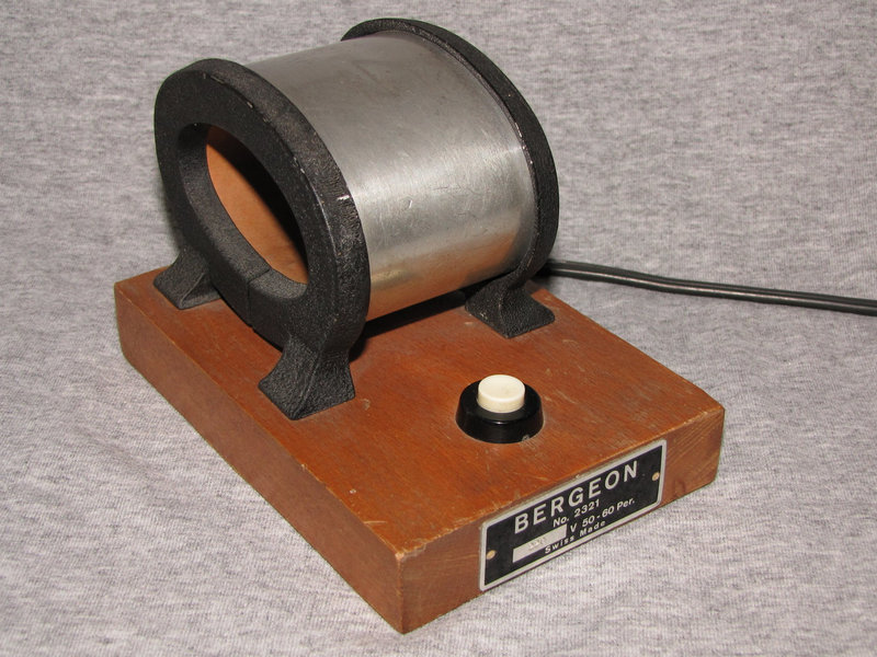
Image to the right shows a very simple mains operated device.
It has a coil which when alternating current is let through creates
alternating magnetic field.
The object that needs to be demagnetised is placed inside the coil,
pushbutton is pressed and the object is withdrawn as far as one can get
it, and the object is hopefully demagnetised.
If not careful, one can easily magnetise objects instead of
demagnetising them.
|
|
|
|
|
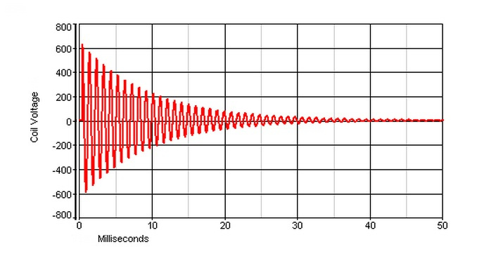
| More
modern devices use simple electronics means of eliminating need for
object removal away from the magnetic field.
This is achieved by creating decaying alternating magnetic field as
shown at the diagram on the right. |
 |
| |
|
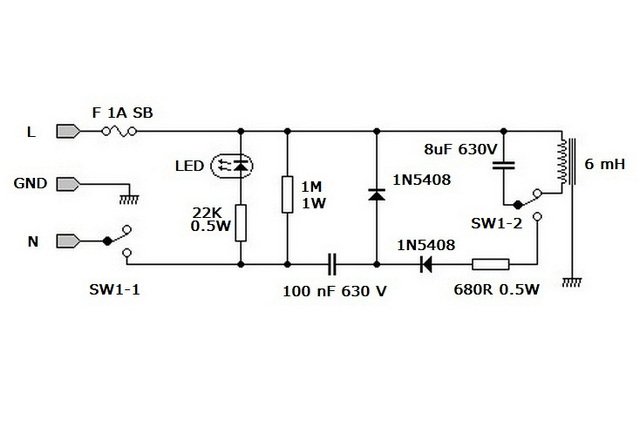
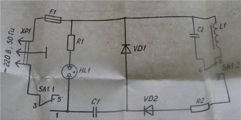
| The
electronic circuit which enables it is quite simple, consisting of a
voltage doubler rectifier followed by an LC resonator circuit.
There is actuating switch, a LED indicator of charge, and a bleeder
resistor which has a task of discharging the capacitor in voltage doubler
circuit, to prevent shock when the unit is unplugged. |
|
| |
|
| To
make this device I have started from an old unit made in SU, the
Soviet
Union many years ago.
Apart from it, I have also checked designs of few other devices
made by Vigor, C&E Marshall and some of the no-name units.
All are very similar to each other. The only difference is between units operated
from 220 VAC as opposed to 110 VAC.
The latter have two stages of voltage doublers, ending with 600 V. |
 |
| |
|
| The
SU original circuit diagram found in a users instructions along with
the list of components. |
 |
| |
|
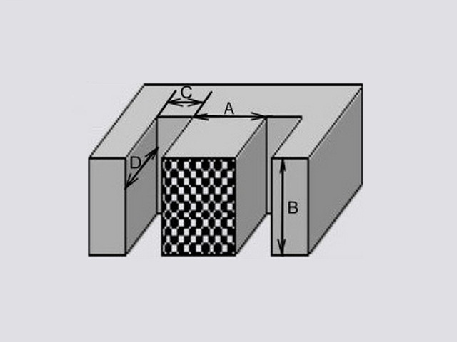
| To
make inductor I have used an old transformer core made up from
"E" and "I" laminations, using only "E"
laminations.
I removed old copper wire windings to make room for new windings
with larger diameter wire, in order to end up with inductance value between 6 and 8 mH,
which was the value used in most of the commercial units tested, including the SU
unit. |
 |
| |
|
| My
transformer had core cross section AxB of 20x20 millimetres. The
coil former took 220 turns of 0.8 mm diameter lacquered copper wire
which produced inductance of 5.8 mH.
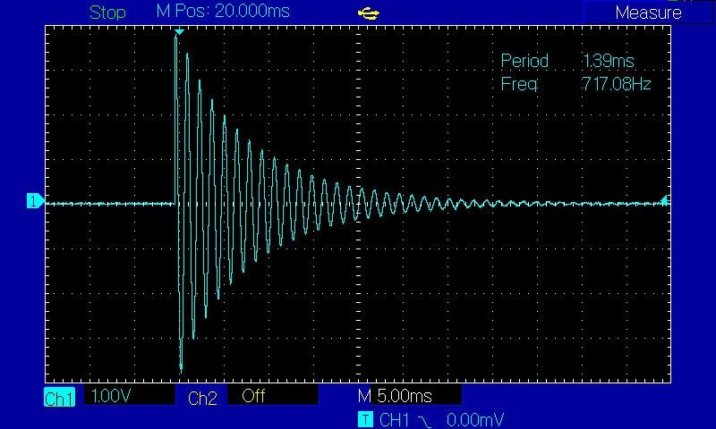
Close enough to get unit to work. Finding a suitable capacitor was
a bit harder. Limitation was set by a high working voltage of 630 V.
The closest that I could find was 8 uF at 630 V, which with
the 5.8 mH
inductor should produce oscillations at about 800 Hz. |
 |
| |
|
| The
actual, DSO measured, waveform of the alternating magnetic field,
sampled by use of an inductive coupling coil.
The oscillogram to the right, shows that the actual operating
frequency of demagnetiser circuit is ~720 Hz. |
 |
| |
|
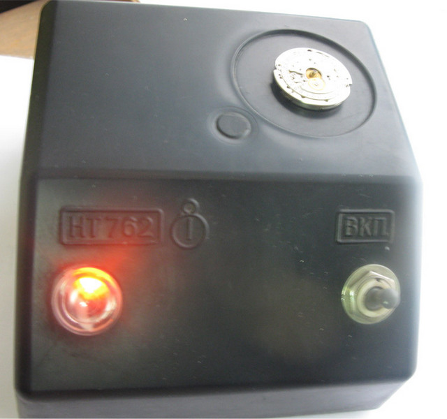
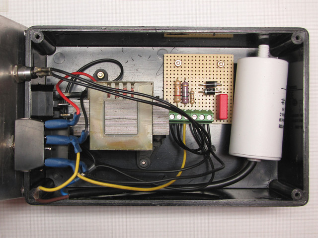
| Unit packed in a plastic box, with an aluminium cover with a round
sticker to mark the centre of the magnetic field action, a LED to show
"Charge Ready".
Unit is normally in the OFF state until switch is set to a charge
position. Only a few seconds later, not more than about five, unit is
ready to demagnetise the watch, accomplished by setting switch to the
ZAP position.
Complete process of demagnetising a watch lasts only a
fraction of a second, about 50 ms i.e. 1/20 of one second. |
 |
| |
|
| |
|
| |
|
| It
should be noted how nowadays the cost of commercial unit is so high
that it warrants validity of going ahead and making one's own unit
which in materials used does not cost more than about fifty to seventy
dollars. The cost of making one is ten to twenty fold lower than
buying a commercial unit, the midrange costing in excess of five hundred
dollars. |
| |
|
|
|
|
|
|
top |
|
|
|
|
|
|
|
|
|

|
|
Copyright © 2004, 2011,
2014, 2015, 2016 by Dushan Grujich. All rights reserved.
|
|
Copyright
Notice
|
| |
|
| |
|
|

Blog Counters
|
| |
|
|
|
| |
|
| |
|
| |
|
| |
|
| |
|
| |
|
| |
|
| |
|