|
We removed the engine to resolve two recurring problems.
The #3 cylinder head fuel injector sleeve had been weeping coolant
for several hundred engine hours. The situation was worsening
and the other two cylinder heads were beginning to show similar
symptoms. The engine was serving notice that it needed some attention.
The repair procedure would require the specialized services of
an engine shop and removal of the cylinder heads.
We also wanted to address another problem that has plagued us
from our early days on the Baja Peninsula, Mexico. Namely, the
recurring failure of the bolts that attach the stbd rear engine
bracket to the engine block. The Westail Corp. had redesigned
the bracket to fit the Volvo engine to an engine room liner that
had been designed for the Perkins 4-108. To effect this, Westsail
lengthened the rear engine brackets. Unfortunately, the added
length also increased the moment arm, amplifying the forces acting
on the bracket. Poor design coupled with lightweight construction
produced an inferior bracket, and excessive movement of the structure
due to vibration resulted. This movement weakened the mounting
bolts over time (cyclic loading and subsequent work hardening)
eventually leading to fatigue and failure.
|
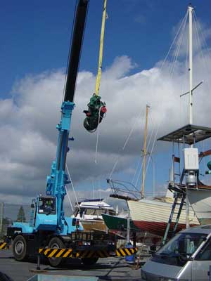
Lifting the Volvo MD3B out of the engine space - the stern of Fluid
Motion (solar panels) is just visible. |
|

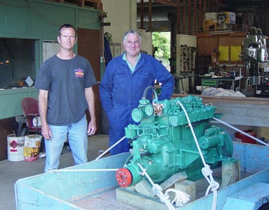
The first order of business was to construct an engine cradle that
would allow us to transport the engine as well as serve as an engine
stand while we effected the necessary repairs. Additional design
requirements included access to facilitate removal of the oil pan
(gasket replacement) and also allow removal of the rear engine brackets.
|

Pictured above is an original rear engine bracket. Note the light
construction and the two mounting holes drilled off-center on a
fairly narrow contact point with the engine. We would like to see
this area widened to distribute the loading and provide a larger
and more stable contact point. The forces on the bracket from top
to bottom of the picture are well-designed for and amply gusseted.
However, the sheering forces from left to right (which would correlate
with forward and reverse thrust) are acting on a weak, unreinforced
axis of the structure resulting in flexion. |
|
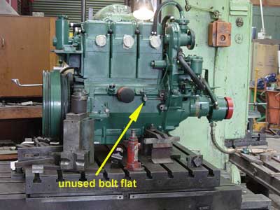
The MD3B engine block has a third engine bracket mounting bolt flat
already cast that was not utilized by Westsail when redesigning
the rear engine brackets. Our new design will incorporate a third
mounting bolt by utilizing this flat. To achieve precise alignment
with the other bolt holes thereby ensuring equal loading across
all three bolts, we have transported the engine to a local machine
shop for the use of their milling machine. |

Wally uses the mill to drill the third mounting bolt flat precisely
parallel to the other mounting bolt holes and perpendicular to the
engine block... |
|
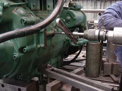
...and finally tapping (cutting threads) the new hole for the bolt.
|
Pictured above is the stbd rear engine bracket in the latter stages
of design. The engine contact point was made wider and a third mounting
bolt added. The effort was duplicated for both sides of the engine.
With the redesigned rear engine brackets complete, we have moved
on to the cylinder head repair and have torn down the top end. |
| At this point, the project has escalated. We had intended only
to remove the cylinder heads for installation of new injector sleeves.
Unfortunately, it proved to be impossible to remove the heads without
disturbing the cylinders as the MD3B features independently removable
heads and cylinder blocks. If the cylinder blocks are disturbed
during removal of the heads, it is likely that oil leaks will develop
at the cylinder block bases at their contact point with the engine
block. Since we were already experiencing some leakage in these
areas, prudence dictated that the cylinder blocks be removed to
facilitate replacement of the cylinder block base gaskets. It was
because of this decision that we discovered damage to the #1 piston. |
In 1985, Volvo Penta redesigned the piston for the MD3B. The design
change altered the compression ratio of the engine (the combustion
chamber is cast into the crown of the piston) as well as the weight
of the piston. The implication for us is that we must replace all
three pistons. At this point, we're into this for a full top end
rebuild including new injector sleeves, valve job, cylinder block
hone, and new pistons and rings as well as all of the incidental
replacements that you have to do just because you did something
else. Of course, we also rebuilt the fuel pump, raw water pump,
fresh water pump, starter, alternator, tanked the cylinders, exhaust
manifold and heads to clean out the water galleries, serviced the
injectors, and replaced a few gaskets to curb various leaks here
and there. |
|
|
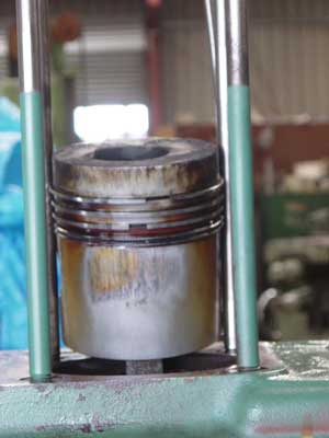
Pictured to the left, the #1 piston has picked up. The scuffs
on the side of the piston are evidence that at some point the piston
has overheated and expanded. The expansion decreased the clearance
between the piston and the cylinder bore. This continued until there
wasn't sufficient clearance for even the thin film of lubricating
oil on the cylinder wall. At this point, the piston scraped the
film of oil off the cylinder wall resulting in engine damage. Although
the piston is still functional, engine reliability has been compromised. |
|

Pictured above, as the pistons and cylinder blocks are installed,
Kev uses a dial indicator to measure the piston-to-head clearance.
Since the combustion chamber is cast into the piston crown, the
clearance between the piston at Top Dead Center (TDC) and the head
must be set up precisely to achieve a balanced compression ratio
between cylinders and to avoid a collision of the piston with a
valve. The compression ratio is then adjusted by adding/removing
shims of various thicknesses between the cylinder block base and
engine block. This, in effect, raises or lowers the cylinder head
in relation to the piston. |
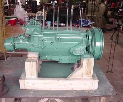
With the proper shim thicknesses calculated to achieve the prescribed
compression ratio for each cylinder, the cylinders and pistons are
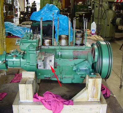
removed to set the ring gaps and paint. Above, the top end and peripherals
are stripped off the engine block. The old engine paint has been
removed, the block and tranny degreased, primed and re-painted.
|
|
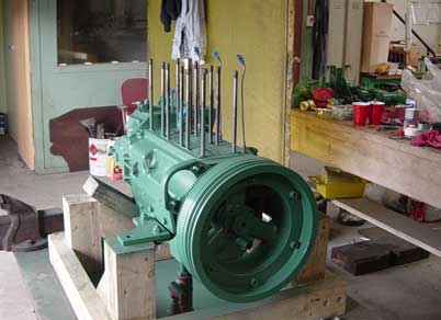
The engine ready for reassembly of the top end |

Cylinder blocks and new pistons and rings installed... |
|

...a view from the top looking down into the cylinder bores. |
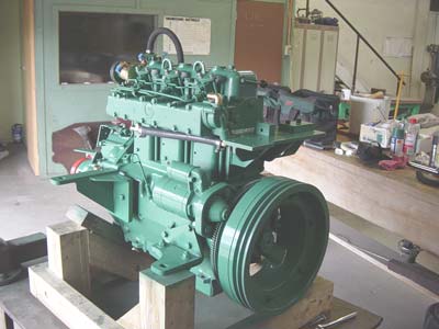
The engine coming together: new pistons and rings, cylinders, heads,
pushrods, tappets, rocker arm assemblies, starter, fuel injectors,
fuel delivery pipes, exhaust manifold and water maker high pressure
pump/reefer compressor bracket assembly. |
|

The last components installed: fine fuel filter, raw water pump,
engine coolant pump and misc. plumbing and fittings. |

Engine repairs complete and ready for transport back to the mother
ship. |
|
Special thanks to Wally for his machine shop services and also for
use of shop space where we were able to complete our work on the
engine. |
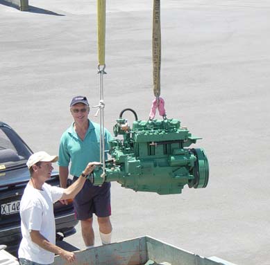
Kevin and Graeme ease the engine off of the cradle as it's craned
up to the engine compartment. |
|

Another beautiful summer day in New Zealand...
A typical summer weather pattern as a slow moving trough dumps for
days, sometimes weeks on end. NZ weather...always an issue. |

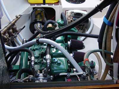
Pictured above, a front view of the engine installation from the
galley/nav area. The companionway steps are removed and doors swung
open to facilitate acccess to the machine space from the cabin interior.
The Volvo affords impressive PTO (power take-off) capabilities with
its enormous flywheel, massive front main bearings and 4 belt grooves.
At fast idle, we easily spin a refrigeration compressor (top left),
watermaker high pressure pump (top right) and high output alternator
(middle right) with at least a 3:1 mechanical advantage. All peripherals
are double-belted with a total PTO requirement of about 8hp. This
makes for a nicely loaded engine achieving full thermal efficiency. |
|

The Westsail 32 features an amply sized machine space (Fluid Motion
sports the optional gelcoated fiberglass liner). Though sacrificing
interior volume, the separate machine space neatly compartmentalizes
the aft section of the boat and affords a centralized location for
our electrical/mechanical devices with the attendant heat, noise
and fumes away from the main living area. |

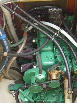
Another view of the engine installation
The machine space centrally locates the engine, batteries, refrigeration
equipment (engine and DC driven), reverse osmosis water purification
system, fuel tanks, alternator, charge regulation components (alternator
and photovoltaic), deck washdown system, water distribution manifold,
fuel transfer system, fuel filtration equipment and crankcase oil
pumpout system. |
|
Looking into the engine/machine space from the galley/nav area |

A view from the aft deck looking down into the cockpit well. The
cockpit sole has been removed for access to the machine space. |
|
...another cool view of the engine :) If only it would stay looking
like this. |
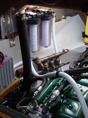
Shown here are the water maker pre-filters and the water distribution
manifold. The manifold couples water vendors (seawater and fresh
from the ships tanks) with multiple subscribers (engine, watermaker,
deck washdown pump and DC reefer water cooled condenser pump). At
any time we can couple the fresh or seawater vendor with any of
the subscribers. This allows us fresh or salt water washdown but
more importantly facilitates the ability to flush our saltwater
systems with fresh water. |