
|
 |
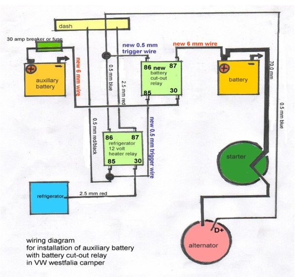
Auxiliary Battery Using a Relay
Simplified wiring diagram for auxiliary (after-market)
battery
installation with a 30 amp relay in a
Volkswagen vanagon Westfalia GL (T3) camper.
Click on diagram below to enlarge.
Things you need for a battery cut-out relay installation
in a vanagon gl westy camper:
1) A section of #12 or 10 gauge, long enough
to go from one battery to the other.
VW uses a 6.0 mm that is close to #10 gauge wire
in some of the weekenders.
You also need a short section of #18 gauge wire.
2) one 12 volt heavy duty 30 amp relay.
3) one 12 volt 30 amp auto reset breaker.
4) four connectors, for the #12 or #10 wire, to connect
the wire to the relay and the auto reset breaker.
5) one batt. ground strap for the aux. batt.
6) two batt.-terminal-connectors to use with the #12 or #10 wire,
for securing it to the + terminal on the aux. and main batt.
7) Two quick splice connectors for small #18 ga. wire,
and two female connectors for # 18 ga wire. The female
connectors have to fit terminals 85 and 86 on the new
battery cut out relay.
(you need this to connect the new battery-cutout-relay
to terminals 85 and 86 on the existing refrigerator-12 volt-
heater-relay) under the driver seat. (GL camper)
If you look carefully, you will see tiny numbers stamped
next to the contacts on the frig. relay.
See diagram for camper with 3 way frig in Bentley.
These wires are used to trigger the new relay, that is, to
make the battery cutout relay go on and off.
8) some plastic ties, and electrician's tape and
a few sheet-metals screws.
The sheet-metal screws are for fastening the new relay in place.
9) a couple of rubber grommets, for routing the 12 to 10 awg wire
through sheet metal.
My guess, total cost of all this maybe $25 to $50.
Optional:
A section of flexible conduit to protect the wire when routing under
the vanagon. I usually use a piece of clear vinyl hose, to protect the
wire from chaffing, where it contacts the body. If the hose is
watertight, make sure it will not collect water.
Buy some electrical putty (home dep.) to seal holes you might have
to drill or to route the wire.
Now all you need is the auxiliary battery.
------------------------------------------------------------------------
How to install the battery cut out relay. Second part.
VW installed such a relay in some vanagon weekender
models in the U.S. The dealer asks $62 for that relay as a spare
part, but there are other sources for similar relays for much less.
Many relays sold have the same number coded connectors VW uses.
It makes the installation more fool-proof to purchase a
relay with the same numbers printed next to the connectors.
85 and 86 for the trigger wire. 87 and 30 for the load.
Some other people have used head light relays.
A good reference and diagram is in 1991 Bentley on page 97.34 a
There you can see both batteries drawn in the diagram and
the battery cut-out relay.
In this application VW used a 6 mm2 wire from the main to the
aux. battery. For a safe installation, one should not use a wire
larger than the 6 mm2 wire VW used.
This battery relay was not factory installed in the westy camper
with the 3 way refrigerator.
Only some of the commonly called "weekender" campers have
the auxiliary battery system factory installed in the US.
This is how the new battery-cut-out-relay
should work.
1) Engine running: Both batteries are connected. Aux. batt.
and main batt. are charging.
2) Engine turned off: The aux. batt. is disconnected from the
main battery.
3) Ignition turned on: The two batteries are still disconnected.
4) Starting the engine: The two batteries are disconnected.
Nr. 4 is important, since the system discussed is only designed
to charge the aux. battery, and not for starting the motor.
VW installed a relay trigger circuit in the camper.
(Trigger circuit means, it switches relays on and off)
One can use this circuit for the new batt.-cut-out-relay.
This will ensure that the batteries are not connected,
while
the engine is started.
It is located at terminals 85 and 86 on the existing refrigerator
relay, under the front seat in the westy camper.
The existing refrigerator-12-volt-heater-relay stays as is.
We only tap into the two small wires, (terminals 85 and 86)
to also control the new batt.-cut-out-relay.
Alteration of the fridge relay setup could drain the battery very fast,
if the engine is not running. (the fridge turns off with the engine
not running when switched on 12 volt, so it won't drain the
battery.)
Summary:
You have to route a new #12 to 10 wire from the + on the
main battery to a auto reset breaker, then to a batt.-cut-out-relay,
and then to the + terminal on the auxiliary battery.
The new batt.-cut-out-relay is triggered by the two
small wires, on terminals 85 and 86 on the factory installed
refrigerator cut out relay. That's It. Simple enough.
......................................................................................
If you want to read more details on how to do the installation:
1) Take out the front seats, and gain access to the front batt.
boxes. One on each side. Test fit the aux. batt. in its box.
If you use a Optima, the terminals should be to the back.
You should have enough space on the right side of the
aux. batt., to install the new cut-out-relay, and the
auto reset breaker.
Also mark where to fasten the batt. ground strap to the
frame, and mark a place to drill a hole for the #12 to 10 wire.
Note the fuel lines, AC hoses etc under the batt. boxes.
2) Take aux batt. out and drill the hole for the #12 to 10 wire.
Remember to use a grommet where it passes through the sheet
metal. Mount the cut-out-relay and the auto reset breaker
on the right side in the aux. batt. box.
I suggest you install a piece of sheet plastic between the
new relay and breaker, and the battery box, so the wires later
don't rub against the metal.
Use the sheet metal screws for fastening.
Install the ground strap to the frame in the batt. box.
3) Cut two pieces of # 18 ga wire, and crimp one
female connector to each and connect them to the trigger
circuit on the batt.-cut-out-relay.
Find the 2 small wires that go to terminals 85 and 86 on the
refrigerator-cut-out-relay. Look in the Bentley for the colors
of these wires. In the 90 westy they are 1) blue 2) red/black
Use two quick-splice-connectors to connect
them to the trigger terminals on the new cut-out relay.
4) Connect the #12 to 10 wire. As the wire enters the aux.
batt. box, first connect it to one terminal on the 30 amp breaker.
Cut a short section of the #12 to 10, to connect the
other terminal on the breaker to terminal 87 on
the new batt.-cut-out-relay.
Now connect a long enough section of #12 to 10 to terminal 30
on the batt.-cut-out-relay, so it can be connected to the + terminal
on the auxiliary battery. But for now, wrap the end in some plastic,
so it does not make ground contact.
Make sure the connections on the new relay and breaker
don't make any ground contact, and are safe.
Route the #12 to 10 wire under the car to the main battery box.
Use cable ties to secure it, and make sure there are no
sharp objects near the wire. Preferably use a conduit,
to give it some added protection. Give the wire lots of
slack.
5) Find or make a opening in the main batt. box to enter
the other end of the #12 to 10 wire. Again use a grommet.
As an option, you can install a second 30 amp breaker
with the #12 to 10 wire next to the main battery.
Now reinstall the main battery, and connect the new #12 to 10
wire to the + terminal on the main batt.
Leave the ground off until
you are finished on the other side.
6) Install the auxiliary battery.
Unwrap the #12 to 10 wire, the one that comes from the
cut-out-relay, and connect it to the + terminal on the
aux. battery.
Now connect the ground strap to the - (minus) terminal
on the auxiliary battery.
Go to the other side of the car, and connect the ground on
the main battery.
To test the operation of the relay:
Disconnect the new #12 to 10 wire at the main battery + terminal.
With the engine off, there should be no current and no ground.
Reconnect the #12 to 10 wire.
On the aux. battery:
With the engine running, the voltage should be higher.
(battery is charging)
Engine off, voltage drops.
Note:
Always disconnect both batteries when working on
electrical system.
If you have a dual batt. system in your van, tell the
mechanic when you take the car in for service.
Keep in mind that for standard wire sizing, as the number
becomes smaller, the wire becomes bigger.
Example, 10 awg is bigger than 12 awg.
VW uses metric wire size. Most electrical wire in stores has
both metric and standard numbers on the package.
Its best not to use a wire larger than 6.0 mm square cross section,
or 10 awg for the charging wire with this relay installation.
Note: Disclaimer: You should double-check everything
with a professional.
But the relay installation is fairly simple and straightforward,
and VW installed such a system in some vanagon weekenders.