home | our design | design code | software | firewire | resources | design team | contact us
14.1 Introduction
The purpose of PLI is to provide the interface between PHY and Transmitter/Receiver. The PLI incorporates the same interface as described by the example given in the Annex J of the IEEE-1394 Standard Document.
Figure 14.1: Block
diagram showing PLI pin connections
|
|||
Table 14.1: Pin Decription of the PLI
Signal |
Name and Description |
| CTRL_PINS[0:2] |
Control pins 0 through 2. Through these lines PLI tells the internal logic about various situations and actions. The brief description of different signals is provided in the table 7.2. |
| LREQ |
This serial interface is used by the PLI to initiate a request. Is also used to request access to local PHY register. |
| CTL[1:0] |
Define the state of interface when being driven by the PLI or PHY (See section 10.4 for description) |
| D[7:0] |
Packet data is delivered via the data lines. The number of data lines used depends on the speed supported . |
| RE |
Read signal to packet memory |
| Stcmp |
Status complete signal to receiver |
| pipe_en |
This signal enables the quadlet assembler |
| reception |
Packet reception signal to transaction layer |
Table 14.2: Control pins (Ctrl_pins)
conditions
Table 14.3: Monitor pins
| 000 | Idle - No operation (default). | |
000 | Idle - No operation (default). |
| 001 | Timeout - Arbitration or acknowledge timeout. | 001 | Sop(Start of process) - Shifts out arbitration request to PHY. | |
| 010 | Ack_receive - Acknowledge is received from responder. | 010 | Transmit - Data is valid on the data lines from memory. | |
| 011 | Receive - Packet is coming from another node. | 011 | Hold - Packet is not ready. | |
| 100 | Won – Arbitration has won. | 100 | reserved. | |
| 101 | Status - PHY is transferring the status information. | 101 | Imm_req - Immediate request to PHY. | |
| 110 | reserved. | 110 | status_R. | |
| 111 | reserved. | 111 | status_W. |
14.2 Some Major
Components of PLI
· Shift register - 17 bits
· Watch Dog Timer
14.2.1 Shift Register
The register carries the type of request provided by the transmitter. When enabled shifts out the request via LREQ to PHY.
Figure 14.2: Timing
diagram of LREQ
|
|
For more description
on the Request type field refer to table J-8 (pg. 348) of the
standard document.
14.2.2 Watch Dog Timer
Watch Dog Timer is used to counts upto the timeout limit of the arbitration and acknowledge process.
Figure 14.3: Block
Diagram of Watch Dog Circuit

Run Timer
![]()
BCLK
Time out
Timeout
![]()
![]() watchdog
watchdog
![]()
![]() Reset
timer
Reset
timer
![]()
Timeout clock cycles
14.2.3 Control
Circuitry
Figure 14.4: Structure
of finite state machine for Control Circuitry
![]()
![]()
![]()
![]()
![]()
![]()

![]()
![]()
![]()


![]()
![]()
![]()
![]() Inputs
Inputs
Next State Logic
Current State
Reg
Output Log Output (combinational)
Clock
(sequential)
(combinational)
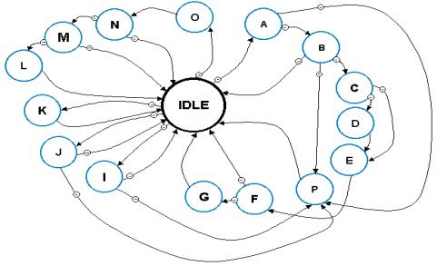
14.3 The PLI State
Diagram
Figure 14.5: The
PLI State Diagram
|
Table 14.4: The State Diagram States
Names
Symbol |
Name |
Symbol |
Name |
Symbol |
Name |
| A |
REQUEST | B |
WAIT_state | C |
WON |
| D |
HOLD | E |
TRANSMISSION | F |
WAIT_ACK |
| G |
ACK_RECEIVE | I |
READ_REQUEST | J |
STATUS_REC |
| K |
IMM_REQ | L |
WON_ACK | M |
WAIT_FOR_GRANT |
| N |
RECEIVE | O |
DATA_ON | P |
LOST |
For more description on the states and the transitions conditions please visit our website.
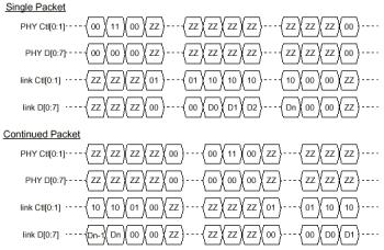
14.4 Waveforms
Following are the waveforms showing communication between PLI and the PHY. For more description refer to clause J-3 of the standard document, page 346.
Figure 14.6: Timing
Diagram for Control and Data lines between PLI and PHY
|
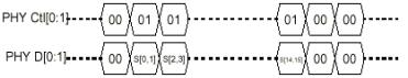
Figure 14.7: Status
Reception Timing Diagram
|
14.4 The Control Pins
Table 14.5: when PHY is driving the
Control Pins
Ctl
[0: 1]
|
Name
|
Meaning |
| 00 | Idle | No activity |
| 01 | Status | The PHY is sending status information to the link. |
| 10 | Receive | An incoming packet is being transferred from the PHY to the link. |
| 11 | Transmit | The link is granted the bus to send a packet. |
Table 14.6: when Link Layer is driving
the Control Pins
Ctl
[0: 1]
|
Name
|
Meaning |
| 00 | Idle | Transmission complete, release bus. |
| 01 | Hold | The link is holding the bus while preparing data or indicating that it wishes to reacquire the bus without arbitrating to send another packet. |
| 10 | Transmit | The link is sending a packet to the PHY. |
| 11 | Unused | Unused |