 |
INFERNO Z24 | |
|
INFERNO Z24 | |
DIAGNOSTIC TROUBLE CODES
The information gathered here on this page is intended for self diagnostics of your computer controlled J-Body 1982-1994 (cavalier, sunbird, skyhawk, cimarron, firenza and J2000)
Computer Command Control System (CCCS) and Trouble Codes.
This electronically controlled emissions is linked with as many as nine other related emissions systems. It consists mainly of sensors and an Electronic Control Module (ECM). Completing the system are various engine components which respond to commands from the ECM. NOTE: 1994 models are equipped with a Powertrain Control Module (PCM). This unit is essentially identical to the ECM in earlier models. General Motors changed terminology to encompass the many functions of this computerized system. In many ways this system can be compared to the central nervous system in the human body. The sensors (nerves) constanly gather information and send this data to the ECM (brain), which processes the data and, if necessary, sends out a command for some type of vehicle (body) change.
Here's a specific example of how one portion of this system works. An oxygen sensor, mounted in the exhaust manifold and protuding into the exhaust gas stream, constantly monitors the oxygen content of the exhaust gas as it travels through the exhaust pipe. If the percentage of oxygen in the gas is incorrect, an electrical signal is sent to the ECM. The ECM takes it and then sends a command to the fuel injectors on a MPFI system, telling it to change the fuel mixture. To be effective, all this happens in a fraction of a second, and it goes on continuously while the engine is running. The end result is a Fuel/Air mixture which is constanly kept at a predetermined ratio, regardless of griving conditions.
TESTING
One might think that a system which uses exotic electrical sensors and is controlled by an on-board computer would be difficult to diagnose. This is not necessarily the case. he computer command control system has a built in diagnostic system which indicates a problem by flashing a CHECK ENGINE light on the instrument panel. When this light comes on during normanl vehicle oporations, a fault has been detected. Perhaps more importantly, the ECM will recognize this fault in a particular system monitored by one of the various information sensors and store it in it's memory in the form of a trouble code. Although the trouble code cannot reveal the exact nature of the malfunction, it greatly facilitates diagnosis as you or a dealer mechanic can "tap into" the ECM's memory and be directed to the problem area.
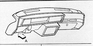
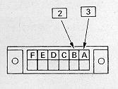
To extract this information from the ECM memory, you must use a short jumper wire to ground a TEST terminal on the Assembly Line Diagnostic Link (ALDL). This terminal is part of an electrical connector located just behind the dashboard, next to the sterring column. A smal, rectangular plate is used to cover the connector and must be pried out of place to provide access to the terminals. With the connector exposed to view, push one end of the jumper wire into the TEST terminal (Terminal "B") and the other into the GROUND terminal (Terminal "A") (REFER TO DIAGRAM). CAUTION: Do Not Start the Engine with the test terminal grounded. Turn the ignition to the ON position (engine not running). The "CHECK ENGINE" or "SERVICE ENGINE SOON" light should flash trouble code 12, indicating that the diagnostic system is working. Code 12 wil consist of one flash, followed by a short pause, and then two flashes in quick consession. After a longer pause the code will repeat itself two more times. If no ither codes have been stored, code 12 will continue to repeat itself until the jumper wire has been discontected. If additional Trouble Codes have been stored, they will follow Code 12. Again each Trouble Code will flash three times before moving on. Once the code(s) have been noted, use the Trouble Code identification information which follows to locate the source of the fault. NOTE: Whenever the battery cable is disconected, all stored Codes in the ECM are erased. Be aware of this before you discontect the battery. CAUTION: If the car is equipped with the Delco II audio system, make sure you have the correct activation code before discontecting the battery. It should be noted that the self-diagnosis featur built into this system does not detect all possible faults. If you suspect a problem with the computer command system, but the CHECK ENGINE or SERVICE ENGINE SOON light has not come on and no trouble codes have been stored, take the vehical to a dealer service department or other shop for diagnosis. Further more, when diagnosing an engine performance, fuel economy or exhaust emissions problem (which is not accompanied by a CHECK ENGINE light do not automaticaly assume the fault lies in this system. Perform all standard troubleshooting procedures, before turning to the Computer Command Control System. Finally, since this is am electronic system, you should have a basic understanding knowledge of automatic electronics before attempting any diagnostics. Damage to the ECM, Programable Read Only Memory (PROM) Calpak or Mem-Cal calibration unit or related components can easily occure if care is not exercised.
| Under Dash Assembly Line Diagnostic Link (ALDL) | |
 |
 |
Trouble Code Identification
Following is a list of the typical Trouble Codes which may be encountered while diagnosing the Computer Command Control System. Also included are simplified trouble shooting procedures. If the problem persists after these check have been made, the vehicle must be diagnosed by a professional mechanic who can use specialized diagnostic tools and advanced troubleshooting methods to check the system. Procedures marked with an asterisk (*) indicate component replacements which may not cure the problem in all cases. For this reason, you may want to seek professional advice befor purchasing replacement parts.
To clear the trouble codes from the ECM memory, unplug the ECM electrical pigtail at the positive (+) battery cable. If the vehicle you are working on does not have this connection, then disconnect the cable from the negative terminal of the battery. CAUTION: If the vehicle is equipped with Delco Loc II audio system, make sure you have the activation code before disconnecting the battery.
Disconecting the power to the ECM to clear the memory can be an important diagnostic tool, especially on intermittent problems. On later models it is a simple matter to unplug the ECM harness psoitive battery cable for ten seconds to clear the stored trouble codes. CAUTION: To prevent damage to the ECM, the igniton switch must be turned OFF when disconecting power or connecting power to the ECM.
| Trouble Code | Circuit or System | Probable Cause | ||
| 12 (one flash, pause, two flashes) | No reference pulses to ECM | This code should flash whenever the Test terminal is grounded with the ignition On and the engine not running. If additional Trouble Codes are stored (indicating a problem), they will appear after this code has flashed three times. With the engine running, the appearence of this code indicates that no references from the distributor are reaching the ECM. Carefully check the four terminal EST connector at the distributor. | ||
| 13 (one flash, pause, three flashes) | Oxygen Sensor circuit | Check the wiring and connectors from the oxygen sensor. Replace oxygen sensor. | ||
| 14 one flash, pause, four flashes) | Coolant Sensor circuit | If the engine is experiencing overheating problems, the problem must be rectified before continuing. Check all wiring and connectors associated with the sensor. Replace the coolant sensor*. | ||
| 15 (one flash, pause, five flashes) | Coolant Sensor cicuit (Low temperatur indicated) | See above. Also, check the thermostat for proper operation. | ||
| 19 (one flash, pause, nine flashes) | Cranckshaft position sensor reference signal intermittent | The reference signal from the crankshaft sensor is intermittent. Inspect PCM harness connector and crankshaft sensor wire harness for shorts or a damaged harness. | ||
| 21 (two flashes, pause, one flash) | TPS cicuit (signal voltage high) | Check for sticking or misadjusted TPS. Check all wiring and connection at the TPS and the ECM. Adjust or replace TPS*. | ||
| 22 (two flashes, pause, two flashes) | TPS cicuit (signal voltage low) | See above. | ||
| 23 (two flashes, pause,three flashes) | Mixture Control (M/C) solinoid circuit (carb. models) | Check the electrical connections at the M/C solenoid.If OK, clear the ECM memory and recheck for code(s) after driving the vehicle. Check wiring connections at the ECM. Check wiring from M/C solenoid. | ||
| 23 (two flashes, pause,three flashes) | Manifold Air Temperature (MAT) sensor circuit (low temp.) | Check the MAT sensor, wiring and connectors for an open. Replace the MAT sensor*. | ||
| 23 (two flashes, pause,three flashes) | Intake Air Temp. (IAT) sensor circuit. (low temp.) | See above. | ||
| 24 (two flashes, pause, four flashes) | Vehicle Speed sensor (VSS) cicuit. | A fault in this circuit should be indicated only while the vehicle is in motion. Disregard code 24 if set when drive wheels are not turning. Check connections at the ECM, Check the TPS setting. | ||
| 25 (two flashes, pause, five flashes) | Manifold Air Temperature (MAT) sensor (high temp.) | Check the resistance of the MAT sensor. Check the wiring and the connectors to the sensor. Replace the MAT sensor*. | ||
| 25 (two flashes, pause, five flashes) | Intake Air Temp. (IAT) sensor circuit (high temp.) | Check the resistance of the IAT sensor. Check the wiring and the connectors to the sensor. Replace the MAT sensor*. | ||
| 26 (two flashes, pause, six flashes) | Quad-Driver Module (QDM) cicuit | QDM's are switches within the PCM used to control various components such as: canister purge solenoid, EGR solenoid, cooling fan relay, etc. Due to the complexity of this system if is advised that diagnosis and repair be left to a dealer service department or other authrized repair facility. | ||
| 27/28 (two flashes, pause, seven or eight flashes) 1994 2.2 L models | QDM cicuits | See above. | ||
| 31 (three flashes, pause, one flash) | Wastgate acuator (Turbo's) | Possible sticking wastegate actuator or wastegate. Also check power to the ignition and or a faulty ECM. | ||
| 32 (three flashes, pause,two flashes) | No alitude compensator voltage (carb. models only) | Check connections at altitude compensator. Check for an open circuit in the wiring from the sensor to the ECM. Replace the altitude compensator*. | ||
| 32 (three flashes, pause,two flashes) | Exhaust Gas Recirculation (EGR) system failure | Check the vacuum source and all vacuum lines. Check the electrical connectors at the ECM and EGR valve. Replace the ECM and or the EGR valve*. | ||
| 33 (three flash, pause, three flash) | Manifold Absolute Pressure (MAP) sensor or circuit | Check vacuum hose(s) from the MAP sensor. Check electrical connections ath the ECM. Replace the MAP sensor*. | ||
| 33 (three flash, pause, three flash) | MAF sensor or circuit | Excessive air flow indicated. Check terminal C on the MAF sensor: it should read about 0.5-volts at idle and 4.7-volts at wide open throttle. Trace the wire back from terminal C and look for open cicuit conditions. Replace the MAF sensor*. | ||
| 34 (three flashes, pause,four flashes) | Vacuum sensor cicuit (carb. models only) | Check the wiring leading to the terminals 20, 21 and 22 of the ECM. Check the connections at the ECM. Check the vacuum sensor wiring and connections. Replace the vacuum sensor*. | ||
| 34 (three flashes, pause,four flashes) | Mass Air Flow (MAF) sensor or circuit | Low air flow indicated. Check terminal C on the MAF sensor: it should be at about 0.5-volts at idle and 4.7-volts at wide open throttle. Trace the wire from the Terminal C and look fot a short to ground. Replace the MAF sensor*. | ||
| 34 (three flashes, pause,four flashes) | Manifold Absolut Pressure (MAP) sensor circuit | Check for an open or shorted to ground cicuit. Check the MAP sensor. Replace it if malfunctioning. | ||
| 35 (three flashes, pause, five flashes) | Idle speed control cicuit (IAC valve) | Idle RPM too low or too high. Check minimum idle speed. Check fuel pressure. Check for leaking injector and obstructions in the Throttle Body. Replace the IAC valve. | ||
| 41 (four flashes, pause, one flash) | No distributor reference signal to the ECM at specified vacuum (carb. only) | Check all wires and connections at the distrubutor. Check distributor pick-up coil connections. Check vacuum sensor cicuit. | ||
| 41 (four flashes, pause, one flash) | Cylinder select error | Remove the access cover on the ECM and check to see that the MEM-CAL, PROM or CALPAK is installed properley. Clear the trouble codes and see if the code resets. If so, replace the MEM-CAL, PROM or CALPAK*. | ||
| 42 (four flashes, pause, two flashes) | Electronic spark timing (EST) cicuit | Check the wiring connectors between the ignition module and the ECM. Reoplace the ignition module*. Replace the ECM*. | ||
| 43 (four flashes, pause,three flashes) | Electronic spark control (ESC) cicuit or Knock sensor (KS) circuit | Check wiring and connectors from the knock sensor to the ESC controllor or ECM for an open or short to ground; if necessary, reroute the harness away from other wires such as spark plugs, etc. Replace the knock sensor*. | ||
| 44 (four flashes, pause, four flashes) | Lean exhaust | Check the wiring and connectors from the oxygen sensor to the ECM. Check the ECM ground terminal. Check for a sticking M/C solinoid. Check the fuel pressure. Check the vacuum for leaks at the carb. base gasket, throttle body gasket, vacuum hoses or intake manifold gasket. Replace the Oxygen sensor*. | ||
| 45 (four flashes, pause, five flahses) | Rich exhaust | Check for a sticking M/C solanoid. Check wiring at the M/C solanoid connector. Check the evaporative chamber charcoal canister and its components for the pressence of fuel. Check for fuel cantaminated oil. check the fuel pressure regulator. Check for a leaking fuel injector. Check for a sticking EGR valve. Replace the oxygen sensor*. | ||
| 51 (five flashes, pause, one flash) | PROM/EEPROM error | Faulty or incorrect PROM/EEPROM. Diagnosis should be performed by a dealer service department or other qualified repair shop. | ||
| 52 (five flashes, pause, two flashes) | CAL-PAK error | Faulty or incorrect CAL-PAK. Diagnosis should be performed by a dealer service department or other qualified repair shop. | ||
| 53 (five flashes, pause, three flashes) | System over-voltage | Code 53 will set if the voltage of the ECM is greater than 17.1-volts or less than 10-volts. Check the charging system | ||
| 54 (five flashes, pause, four flashes) | Mixture control (M/C) solenoid (carb. only) | Check all M/C solenoid and ECM connections. Replace the M/C solenoid*. | ||
| 54 (five flashes, pause, four flashes) | Fuel Pump cicuit | Ceck the fuel pump relay cicuit and connections. Check the oil pressure switch. Repair/Replace faulty components*. | ||
| 55 (five flashes, pause, five flashes) | ECM/PCM | Be sure the ECM/PCM ground connections are tight. If they are, replace the ECM/PCM*. | ||
| 61 (six flashes, pause, one flash) | Contaminated oxygen sensor | Replace the Oxygen sensor*. A contaminated sensor can be caused by fuel additives containing silicon or non-GM approved sealent or lube. | ||
| 62 (six flashes, pause, two flashes) | Transaxle gear switch signal circuit | Check for an open cicuit with a voltmeter at the TCC connector. Voltage should be about 12- volts. Further diagnosis is best left to a dealer searvice department or other repair facility with the proper diagnostic tools. | ||
| 63 (six flashes, pause, three flashes) | Manifold Absolut Pressure (MAP) sensor circuit (low vacuum detected) | Check wiring and connections from the MAP sensor to the ECM. Check the vacuum hose to the sensore for leaks. Replace the MAP sensor*. Replace the ECM*. | ||
| 64 (six flashes, pause, four flashes) | Manifold Absolut Pressure (MAP) sensore circuit (high vacuum detected) | Check the wiring and connections from the MAP sensor to the ECM. Replace the MAP sensor*. Replace the ECM*. | ||
| 66 (six flashes, pause, six flashes) | A/C refrigerant pressure sensor circuit | Check the sensor electrical terminal connections and for a possible short to ground open circuit in the sensor wiring. Replace the A/C refrigerant sensor*. | ||
This page last updated May 28, 2000