THERMAL PHENOMENA AND THE DESIGN OF A FORCE TRANSDUCER
YU.P.
STEPANENKO
Research
Institute of Mechanics and Applied Mathematics,
University of Rostov-on-Don,
ul. Stachki 200/1, 344104 Rostov on
Don, Russia
L.P. LEBEDEV
Dept. of mechanics and mathematics,
University of Rostov-on-Don,
ul. Zorge 5, 344090 Rostov on Don, Russia
It is well known that while under a load, an elastic body is deformed and its temperature slightly changes over time, this change, along with thermoconductivity, results in additional deformation resembling the creep under load. Load transducer designers mistakenly include this deformation into the evaluation of the metal creep. The ineffective design and the loss in metrology properties of a load transducer are consequences of this mistake.
Some thermal phenomena and their consequences for the design of a load transducer are discussed.
![]()
Key words: creep, thermoelasticity, load transducer, spring element, calibration beam
1. Historical remarks
In 1830, Wilhelm Weber carried out an outstanding investigation of thermal phenomena in stretched metal strings. 4 years later, in 1834, Louis Joseph Vicat performed the first tests of the steel creep. Each mechanic is now aware of the steel creep, at least he is aware that a thread connection has to be tightened from time to time. It seems, however, that only a narrow circle of specialists in thermoelasticity believes that thermal phenomena will have to be taken into account during the design of a precise measuring device.
2. Notation
t0 Time when the load is increased until it reaches the work constant value
t Loading time by a constant work force;
the reference point of the time is the end of
transient period of the increase of the force
T0 Initial temperature of the device
DT Theoretical change of initial temperature under the load
D![]() Experimental change of initial temperature under the load
Experimental change of initial temperature under the load
3. Numerical estimations
Neglecting the thermal phenomena in an elastic body causes a method error in the estimation of the creep within the main elements of a load transducer. Measurement of the creep of the components of a load transducer is carried out with relative accuracy up to the thousandth of one percent [1] whereas the thermal phenomena involve the tenth of one percent.
We will clarify the problem considering a load transducer DT-100 (the work range is 100 kN, the loading time ranges from 10-3 s to 103 s) which is exploited in a system of road control in Russia. The tests of the creep of the elastic sensing element of the load transducer are performed under the constant load 100 kN. The work load is reached for the time t0 that is for no more than 1 minute. Under the load, the temperature and the strain in the middle part of the sensing element are both measured for several minutes. Fig. 1 presents the sensing element and the mechanical diagram of its loading.
М 1:2
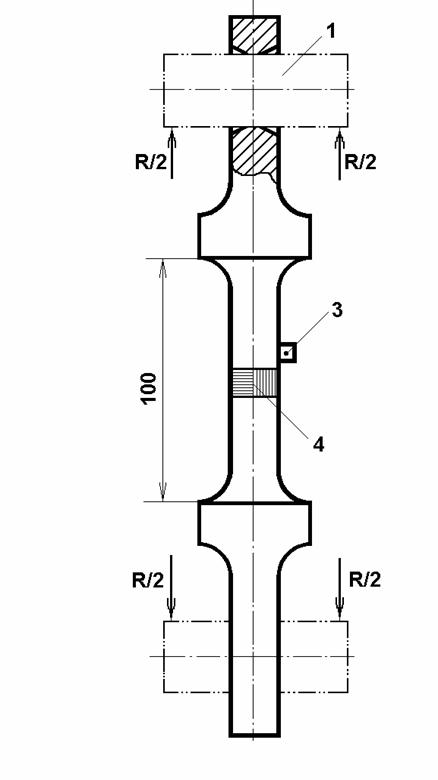
Fig. 1 The sensing element of load transducer DT-100 with a mechanical diagram of loading
1 The force transmitter shaft under the load R
2 The sensing element made of alloyed steel (0.3%Ñ, 1.2% Cr, 1,5% Si)
3 The temperature gauge
4 The full bridge with four measuring grids
Numerical simulations and the comparison with experiments show that the transient load process is adiabatic. By the end of the transient process, under the force 100 kN, there is a fall in temperature of 0.28°C in the middle part of the sensing element. Then because of thermoconductivity, the temperature rises up to the environment temperature; this is the passage from the adiabatic regime of deformation to isothermal one that we call ST passage. In theory, ST passage lasts for an infinite time but in practice, it completes in 15..20 minutes. The moment when the load reaches 100 kN, the strains in the sensing element increase for 0.22% for this time. This slow increase resembles the metal creep but it is another phenomenon. The ST passage is described using the relations of thermoelasticity with reasonable accuracy; the equations can be found in [2, 3]. The finite difference method is used to calculate a solution to the corresponding initial-boundary value problem. For a node of jump-change of the cross-section of the sensing element, the condition of heat balance is applied.
![]()
![]()


![]()
![]()
![]()
![]()
![]()
![]()
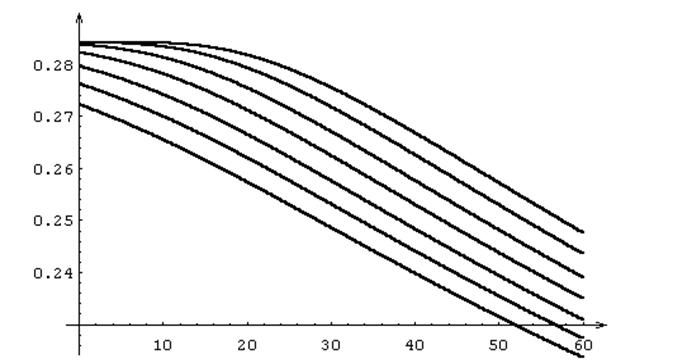
Fig. 2 ST passage in the sensing element of load transducer DT-100;
T0=12°C
is the initial temperature;
DT is
the change of temperature in the loading process;
time t0 of load increase is 1, 10, 20, 30, 40, 50, 60
seconds respectively for the curves; t refers to the end point of load
increase period
The numerical results (Fig. 2) demonstrate that the dependence of the initial change of temperature in the middle part of the sensing element on t0, the time of loading up to 100 kN, is practically absent.
![]()

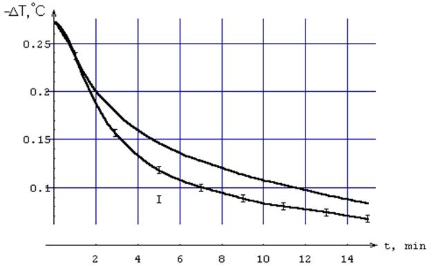
Fig. 3 ST passage in the sensing element of load transducer DT-100, the theory and the test; t0 = 30 s
Fig. 3 presents the further development of the temperature of the sensing element under the load. It is seen that the theoretical adiabatic change of temperature at the start moment of measuring approximates the experimental value with reasonable accuracy. In other moments, the difference between the theoretical and experimental values is due to simplifications of boundary conditions for the model of the element. The time decrement of ST passage depends on the square of the typical size (here it is the length) of the sensing element, whereas the relative change of the strains is constant.
Thus the experimental “creep” includes a thermoelastic component; to estimate the value of real metal creep, this component must be taken out from the measured value.
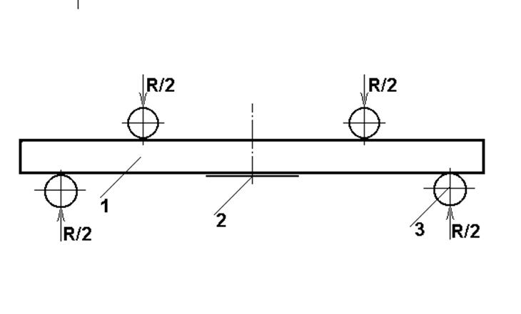
Fig. 4 Mechanical diagram of loading a calibration test bed
1 The steel beam
2 The strain gauge under investigation
3 The load transmitter element under the force R/2
A similar error is typical to investigations of the creep of a strain gauge. A strain gauge is usually glued onto a steel calibration beam (Fig. 4). Rather fast (adiabatic) loading of the beam (until the regime of a given deformation) is accompanied with the change of temperature of the metal. The strain gauge subtracts the temperature component of strain automatically. During the ST passage, the thermoconductive process of stabilising the temperature, the initial value of the signal of the thermocompensated strain gauge decreases in the value for about 0.2%; this decrease is usually taken for the creep. Measuring of the gauge creep starts when the system becomes quiet. In the literature (see [1], e.g.), the moment of the beginning of measurements is not usually shown but in any case, some part of the ST passage is involved into the experimental data and usually relates to the creep. As an example, consider the ST passage for a steel calibration beam of 20 mm in thickness (Fig. 5).

![]()

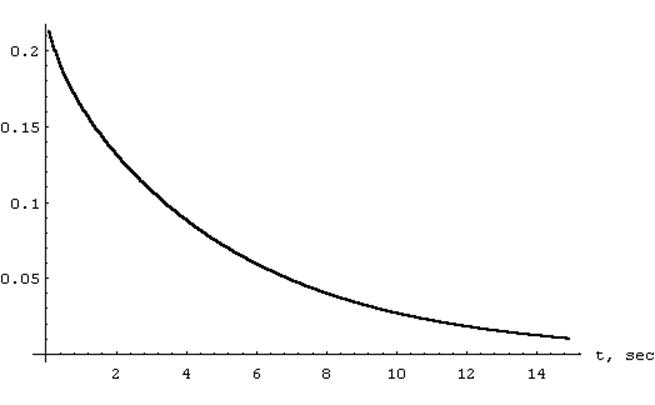
Fig. 5 ST passage in a Calibration test bed instantly loaded by a constant force;
the beam material is an alloyed steel: 0.3%Ñ, 1.2% Cr, 1,5% Si; the beam thickness is 20 mm; the equilibrium value of strain e0= 1.5 10-3
Let the beam be instantly loaded by a constant force. For the next 20 seconds, the initial adiabatic deflection gives the rise for 0.19%, that is practically the full ST passage. For the beam of 100 mm in thickness, the time characteristics is 25 fold of the characteristics for the former beam. To estimate the creep of a strain gauge, the measuring value must be reduced by a part corresponding to the ST passage.
4. Two examples
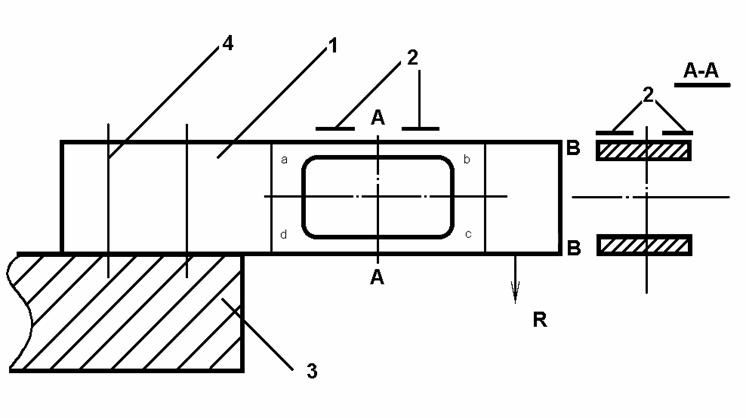
Fig. 6 The loading mechanical diagram of a force transducer of parallelogram type
1 The spring element of the force transducer
2 The strain gauge
3 The adapter plate
4 The tightening screw
Example 1. There is a remarkable design of a load transducer of parallelogram type (Fig. 6). This construction, intentionally or by chance, compensates all the factors [1, 4] affecting on the accuracy, among them the influence of thermoelastic phenomenon. The symmetry of active zone a-b-c-d with respect to three marked planes (one of which is A-A) provides insensitivity of the transducer to the torque and a horizontal force. The full bridge of four measuring grids is included into the picture keeping the symmetry. By individual adjusting of the spring element and the additional correcting for the creep influence, the error of the load transducer reduces to 0.01% for the work load 1 kN. Unfortunately, the best intentions bring some difficulties into the nice picture.
Difficulty 1. The device is employed in the work range of tens and even hundreds kilonewtons. The criterion of similarity fails now as the contact strength of the support elements (adapter plate) has to be ensured and so, on the rise of work load, the boundary stresses penetrate inside the spring element. The above-mentioned active zone extends although it was not supposed and the symmetry of the picture is more and more approximate. All the negative factors affect on the accuracy greater, the thermal factor among them. The construction goes from the series of remarkable to good or even to rather ordinary.
Difficulty 2. The strain gauges (measuring grids) are taken off and a contact-free displacement transducer to measure the vertical displacement is installed in the plane B-B. Now the thermal phenomenon works in full measure. The construction can be “saved” only by the use of adiabatic or isothermal regimes and the requirement to provide the identity of testing and working load regimes.
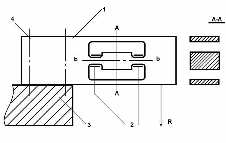
Fig. 7 A force transducer with in-built transducer of vertical displacement of points b-b
1 The parallelogram type spring unit under load
2 The strain gauge
3 The adapter plate
4 The tightening screw
Difficulty 3. The strain gauges move to the in-built span (Fig. 7) which takes on a role of a vertical transducer of the relative displacement of points b-b. The compensation of all the influencing factors is stronger except the factor of thermoelasticity. Really, because of a big difference in the time characteristics of the ST passage in the active zone a-b-c-d and the span, the influence of thermal phenomenon appears to be significant.
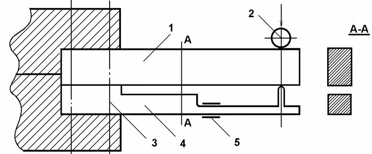
Fig. 8 A force transducer having a transducer of the cantilever deflection
1 The spring unit (bending beam) of the force transducer
2 The adapter unit loaded by force R
3 The tightening screw
4 The bending beam of the displacement transducer
5 The strain gauge
Example 2. Fig. 8 presents a load transducer embodying the top of misunderstanding of the of measurement nature. Leaving aside the influence of bad mechanics of the device on the accuracy, we notice that the thermal phenomenon affects rather significantly by the same reasons as in the first example.
Notice again that the reading of a thermocompensated load transducer is automatically reduced for the value of thermal strain, so the transducer shows the reading that corresponds to the isothermal part of the deformation of spring element. Thus the exact investigation of the creep of a spring unit with use of laser interferometer [1] carries less information than the work testing of the transducer.
A thermally compensated load transducer reduces the influence of the ST passage on the measurement accuracy but outside the designed range of applications, when the spring unit loses the property to be thermally compensated, the above mentioned 0,22% directly affects on the accuracy of measurements.
The noncompensated part of the thermal phenomenon and the creep are of regular nature, their influence can be reduced by a specific design and the use of computer since their analytical structure is known. In this case, there is no necessity in the identity (or similarity) of the work loading process to the testing one, about which (the identity) the firm catalogues [5, 6, 7, 8] keep silence. In general, it is impossible to provide the identity of the two processes. For example, for the load transducer TD-100, the characteristic time of the work loading is 0.1 s (with the step 0.001 s) whereas for the testing it is 1000 s (with the step 10 s). If the analytical structure (or physical nature) of affecting factors is unknown then it requires years to get the needed accuracy of a load transducer technologically since its polishing is performed at random.
5. Some advice to the designer
* Choosing a material for the spring element, under other equal conditions, one has to select the material with minimal ratio of the thermal coefficient of expansion to the specific heat capacity as the change of temperature in the ST passage is proportional to the ratio.
* To regularise the heat flow of ST passage, it is necessary to move the contact support (adapter plate) as far of the active zone as possible.
* In the choice of a spring element of load transducer, a favour has to be done to a thermocompensated strain gauge.
* For rapidly oscillating loading, one has to correct the influence of ST passage with a computer coding.
ACKNOLEDGEMENTS
The authors are grateful for the financial support provided by Russian Fund for Fundamental Investigations (grant no. 95-01-00584a).
APPENDIX
REFERENCES
1. Klokova, N.P., Strain gauges, 1990 (Mashinostroenie, Moscow), 224 p. (in Russian).
2. Lurie, A.I., Theory of elasticity, 1970 (Nauka, Moscow), Chapter 3 (in Russian).
3. Rabotnov, Yu.N., Mechanics of a solid, 1979(Nauka, Moscow), Chapter 2 (in Russian).
4. Pople, J., ‘Errors and uncertainties in strain measurements employing metallfoil gauges’, Transducer Tempcon Conf., Harrogate, 1984, vol.27, Tavostock, 523-574
5. Avery Berkel Catalogue: Load Cell Technology; UK, 1996, 1-11
6. HBM Catalogue: Load Cells & Force Transducers & Survey, Germany, 1995,1-12
7. Philips Catalogue of Load Cells, Germany, 1995, 1-23
8. Revere Transducers: Load Cell Guide; USA,1995, 1-4