This project is a proposed ignition module design to replace the stock unit for a 1980 Honda CB 750 C motorcycle. It uses two GM HEI igniter modules. The parts for this project should not cost much more than $35. This module is designed to work with the stock inductive pickups and the stock spark coils. This module will also work as a replacement for the many other early 1980's Honda CB motorcycles that use the same pickups, rotor, and coils as the 1980 CB 750 C. It uses a mechanical advancer unit. This project is not compatible with electronic-advance type ignitions.
Background:
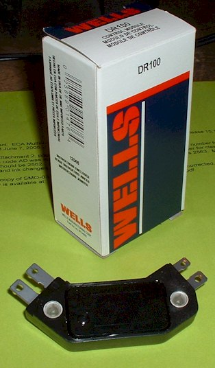
Because the CB750 has an inline, 4-cylinder engine, it requires two spark coils, two pickups, and thus, two igniter circuits. This replacement module (as well as the stock unit) actually contains two separate ignition circuits using two HEI modules acting independently. This is what the HEI modules look like:
The Honda pickups put out a signal that has a significant amount of "crosstalk" between the two pickups. The signal has a large primary signal to trigger the spark, but there is also a small secondary signal when the opposing pickup is triggered. The two signals are 180 degrees apart on the crankshaft. If the signal is boosted by enough DC offset, or "bias", the secondary signal is strong enough to create a second, unwanted spark. Because the secondary signal is inverted, the unwanted spark does not happen 180 degrees away from the desired spark, but happens later, at about 135 degrees before the desired spark. This causes the obvious problem of misfires and backfires because the crosstalk triggers the unwanted spark early in the compression stroke. This can lead to a lot of damage because it duplicates the conditions of knock or pre-ignition if ignition takes place.
Simply reducing the DC bias would appear to be a solution to eliminate the unwanted spark. The problem is that this causes the dwell for the desired spark to be too short. By reducing the bias, the onset of dwell gets held off for an additional 75 degrees of crank rotation.
Another solution would be to increase the bias such that the crosstalk signal won't be able to cross the end-of-dwell threshold. The problem with this is that the bias would put the igniter into an "ambiguous" state (please refer to the HEI notes) at rest. This may result in a state where the coils are "on" all the time when the engine is not running. It would also fix the dwell angle at 180 degrees, which would unnecessarily heat the ignition coils at low RPMs and waste power.
Proposed Solution:
The proposed solution eliminates the unwanted sparks by attenuating the signal. This reduces the amplitude of the crosstalk such that it won't be able to cross both thresholds regardless of the amount of DC bias that is applied. An external voltage divider can be constructed to reduce the amplitude of the signal. However, it is not necessary to construct an external one because the HEI has an internal structure that will accomplish the same task. Inside the HEI, there is a large resistance connecting the G terminal to the W terminal. There are also large resistances connecting the G terminal to the input comparator and the W terminal to the dwell control circuit. These resistances act as a natural voltage divider, which reduce the amplitude accordingly. It is not known what the actual values of the resistances are because they are internal. A schematic of the HEI module suggests the W to G resistor is 10K and the other two are 20K ohms.
The attenuation also relies on the fact that the W terminal's voltage is allowed to "float". In other words, the voltage on W is not solidly fixed by the dwell-control circuit. The current through the W terminal's 20K resistor causes the W terminal's voltage to go negative when the pickup signal is positive. This produces a natural negative-feedback effect on the W terminal. This comes in handy to help reduce the positive amplitude of the pickup signal. However, this will not happen if the W terminal is directly connected to the external bias voltage. R1, D1, and D2 create the 1.4v bias voltage at the R1-D1 junction. R2 and R3 are used to connect the bias voltage to the pickup without forcing the W terminal to be fixed at 1.4v. When no signal is present, W is at 1.4 volts, but W can vary, as described above, when a signal is present.
However, attenuating the signal, while eliminating the unwanted sparks, will not fix the problem of the dwell being too short at higher RPMs (as mentioned above). The dwell will still only top out at 90 to 100 degrees. To increase the dwell at higher RPMs, the HEI's variable dwell scheme will be applied which automatically increases the DC voltage on the W terminal at higher RPMs. (This is described in the HEI notes.) R2 and R3, thus, serve a second purpose besides allowing the W terminal to provide negative feedback. They also limit the HEI's variable dwell voltage. Normally, W would start at about 1.2 volts and could increase up to about 7or 8 volts. R2 and R3 are selected such that the voltage on W starts at about 1.4 volts and increases only to 1.7 volts. This is all that is necessary to increase the dwell sufficiently. The reason such a small change in bias voltage is all that is needed to produce a large change in dwell angle is because the crosstalk artifact is being taken advantage of.
Because the crosstalk was reduced, but not eliminated, it still affects the onset of dwell. It still has a small positive "bump" which will cross the onset-of-dwell threshold (but now it won't have enough "trough" to cross the end-of-dwell threshold). The bias need only boost the DC level of the bump slightly, to make it cross the onset-of-dwell threshold. The result is that, as the bias voltage on W increases slightly, the dwell suddenly jumps from about 80 degrees to about 180 degrees (more than doubling the dwell time). This happens somewhere between 3000 and 4000 RPM (when gap is .6mm), but the actual point is determined by the gap at the reluctor's pickup.
Results:
The final dwell structure is as follows:
At 1300 RPM, the dwell time will be about 8 msec.
As the RPMs increase to 3500 RPM, the dwell reduces gradually to 4 msec.
At 3600 RPM the dwell jumps back up to 8 msec, which is 180 degrees of crank rotation.
Above 3600 RPM, the dwell angle remains at 180 degrees.
This means as the RPMs increase to 10,000 RPM, the dwell time gradually reduces to 3 msec.
This project has the same delay characteristics as the stock ignition. (Please refer to CB ignition notes above for details on the delay characteristics.)
Construction:
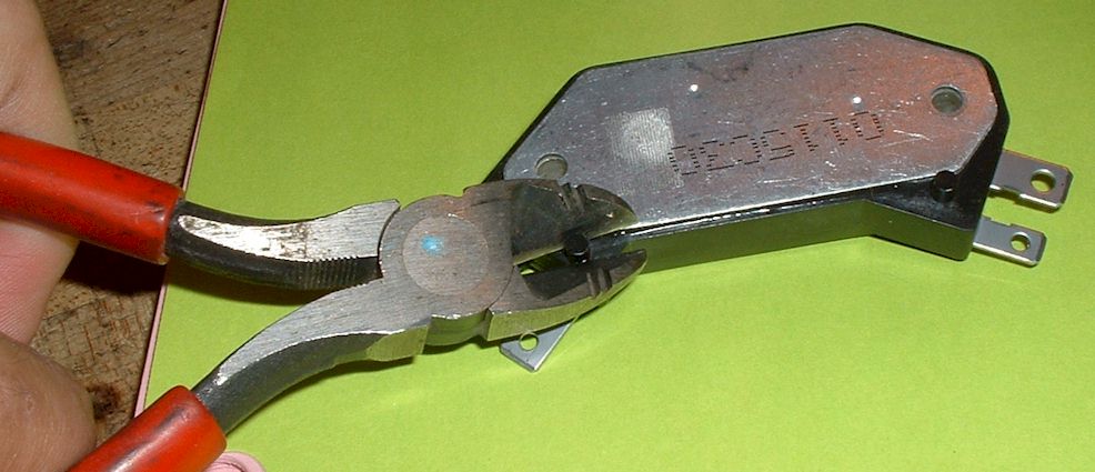
The construction of the project is simple, but first you have to clip off the two locator pins on the bottom of the modules.
Then just mount the two modules on to an aluminum plate using the supplied thermal gel and appropriate bolts. The plate needs to be at least 1/8 inch thick to be rigid. It should probably have at least about 16 square inches of surface area for adequate cooling. (It only gets slightly warm). The bolts will act as the ground connection. Next solder or use connectors to attach the wires. The 5 external components can simply be soldered and wrapped in tape. Make sure the polarity is correct on the two diodes by paying attention to the stripe on the diodes. The resistors can go either way.
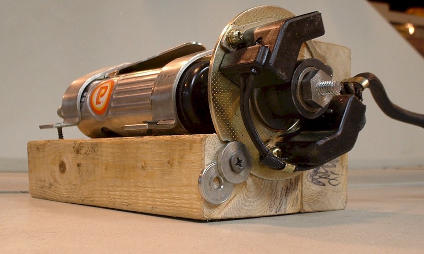
This project has been tested extensively using a test rig to run the reluctor. It hasn't been tested on a real engine yet.
Here is the test rig: