A giant S-G type seismometer
This page shows pictures of a homebrew amateur built horizontal seismometer
which uses a linear Hall sensor and
eddy current damping via aluminum plates. Along with an amplifier
created by Robert Lamb; home computer, p-c card and programs; these additions
comprise a seismograph.
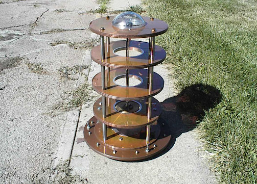
OH...the compasses are going crazy! Alien spacecraft!...NO...just
surplus material. The seismometer
pictured above is not meant to be duplicated; but to only convey
the general construction makeup. The
round disks as shown are actually old aluminum computer main frame
hard drives stacked together.
The mass is out of a old large tape recorder, weights 4 pounds,
and originally was a enertia wheel. Overall
this seismometer weighs 37 pounds. The upper disks are 10
& 1/2" in diameter. The base disks are 14"
in diameter. The height is 20". It is structurally enough
to stand on with no resulting damage. If you
decide to homebrew your own version regardless of size aspects,
make the basic frame as structurally
strong as you can, and use no magnetic materials on the boom or
mass. For temperature change reasons,
it would be a good idea to use, say, mostly aluminum. This seismometer
uses a combination of aluminum,
brass and stainless steel with little or no magnetic properties.
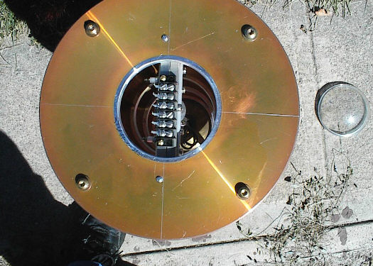
The above is the view looking down from the top, with the plastic
removed (on the ground). Note the
terminal block is only fastened to one rectangular rod underneath.
The other rectangular rod is used to
squeeze the thin brass shim stock by compression; which in itself
is compressed below the view by
another set of blocks that are rigidly attached to the boom.
As a whole, the boom and mass pivot from
this junction, and the earths movements are sensed from this lack
of enertia. (The mass will tend to stay in
its place in space, while the frame and earth move.) The pointed
objects coming off the left side of the
terminals are solder lugs. Between the lugs and boom connections,
are run fine wire which is left hanging
in space, but not touching each other. Presently, I only use
3 terminals/lugs/wires which run to one Hall
device, although the seismometer actually has two Hall sockets....one
for velocity, and one for
displacement. On the top of the disk, can be seen some awl
scribe marks. The hard drive disks do have a
fine iron oxide coating, and aside from scribing convenience, the
coating offers some aluminum
oxidation protection. (Gosh...its too spiff to paint...ha.)

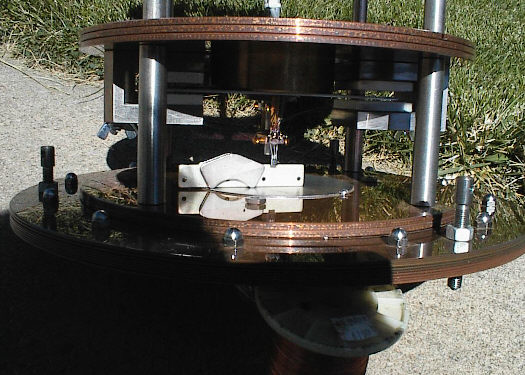
The above is a side view of the hinges and boom/cables. The
hinges as shown are actually "shipping"
hinges, about .025" thick. When the seismo is put on a pier,
two metal spacers are inserted under the
damping plate; this then allows removal of the "shipping" hinges,
and then the real hinges of .001"
thickness by 1/4" wide are inserted very gingerly and locked into
place by the seven shown screws.
After that the metal spacers are removed gently, and the mass moves
free relative to the earths movement.

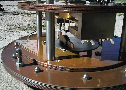
Ahhh...the business end of the seismometer at last! The above
shows the lovely brass mass (ha), the two
damping magnet assemblys, the tiny linear Hall sensor hanging down
from the mass and underneath that
on the base is a round magnetic steel plate to which the sensors
magnets are slide onto and moved
according to sensor output zero position. This view is the
best for seeing the damping plate (1/16" thick)
between the samarium magnet assemblys. I used 1/4" brass shaft
couplers with setscrews to adjust the
mass vertical position on the boom. The mass can also be rotated
around the boom to adjust the
aluminum damping plates for the degree of damping desired.
In the view shown, I used four columns of
stainless steel spacers, instead of three, as it allowed a more
ready access to the Hall sensor, and increased the frame strength.
Also in the view one can see the three base plate adjustment screws
around the outside perimeter. Initial setup is done with a
carpenders level. Although the Hall sensor is
based on magnetic field change; the damping magnets fields above
are limited by the steel in their
respective holders.
The view above shows the Hall sensor (it looks like a three terminal
transistor) and its two surplus
computer neodymium magnets with a aluminum spacer in between.
The Hall is simply plugged into a 8 pin
IC socket in this case (only use 3 sockets). The neodymium
magnets are moved out of position simply for
a view of the Hall. The base plate accomodates the 3 adjustment
screws with drilled and tapped holes.
The nuts on the adjustment screws, (both above and below the base
plate), are important "locking" devices, and should always be used; turned
finger tight against the base plate on final setup. Remember..
the 3 points of the adjustments screws have to carry the weight
of the entire instrument. Most screws in
threaded holes wobble around and move quite easily....without locking
nuts.

The view above shows the neodymium magnets (four pole variety),
centered under the Hall sensor. The
Hall is not touching either magnet. Although not shown, the
base plate also contains the original
computer aluminum hub is underneath the base plate and is withing
the area of the stainless steel spacer
columns, and is actually about 1 & 1/2" thick. Structurally,
the base plate supports the rest of the frame,
and MUST BE stronger than the rest of the frame. If it isn't,
than the mass can drift over time.
The view above shows another angle of the previous photo.
In this view the sensing direction is both
toward and away from the viewer.
Back to the main
page