990603-007a
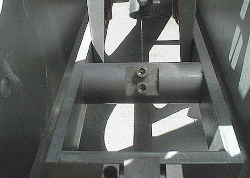
The front of the boom minus the 2 mass plates. In the center is shown the lock in setscrews for the springs wire.
990603-008a
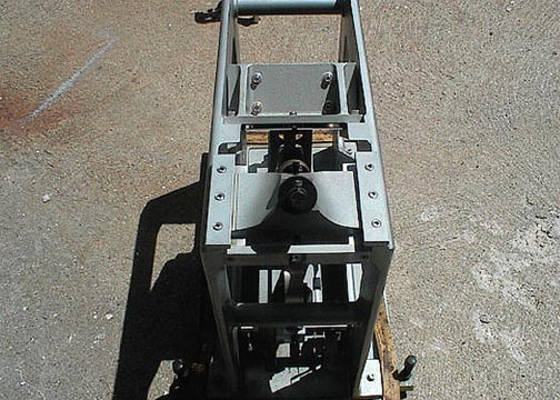
The top rear view of the seismometer. The round
black knob is the spring adjustment screw. About in the middle is
the bracket that holds the two magnets for the coils (not seen in this
view).
990603-009a
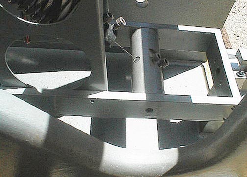
Another view of the front side of the spring wire
locking device. Again the 2 mass plates have been removed for clarity.
The mass plates are mounted on either side of the boom round spacer as
seen.
990603-010a
Another view of the rear boom hinge blocks.

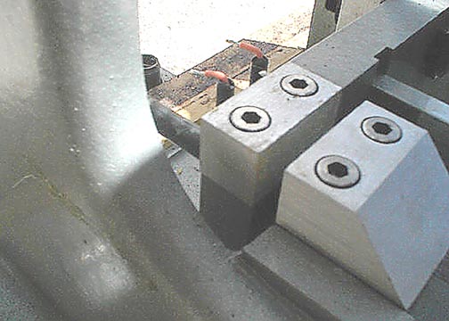
990603-011a
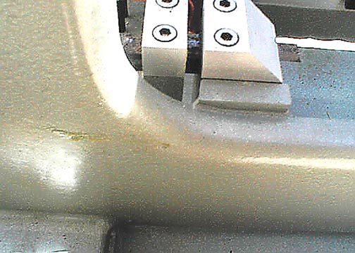
Another view of the hinge clamping blocks for the
2 hinges.
990603-012a
Another view of the clamping blocks. On the
rear is a protruding round pin...this is used to clamp the boom from moving,
till ready for use.