A Diamagnetic Seismometer Experiment
5/16/2000
by Meredith Lamb
000529-01a
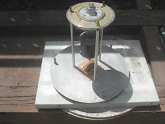
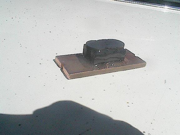
The seismometer above operates very much like a S-G type seismometer,
except that there is no physical "boom", the diamagnetic graphite "floats"
a neodymium magnet in a roughly directional channel within the graphite.
The large black colored object midway down from the top are actually ferrite
magnets on a threaded rod, which is adjusted up or down to help adjust
the height of the levitated magnet. Like all magnetic masses, alot
of problems arise because it is magnetic. In the picture, no wires
from the Hall sensor are shown. For a practical seismometer, I would
not recommend this approach, it is too expensive overall and very time
consuming to achieve even a limited result, with little real useful output.....however,
its "different", and therefore somewhat interesting in itself.
A background reference and credits.
Thanks go to John Lahr, Charles Patton and Robert Lamb for their
assistances over time in relation to this project. John Lahr introduced
me to this diamagnetic subject back in 1998, and whom maintains a steady
interest. Charles Patton introduced me to a key model machine in
mid 1999, and was key to obtaining some diamagnetic bismuth material, which
although it has been superceded by superior graphite since, it did substantially
create a more hopeful atmosphere in obtaining better diamagnetic material.
Robert Lamb has had a long time interest in diamagnetism, and has delved
alot into the details of diamagnetics, and with whom I've shared many notes
and materials over quite a span of time. Here; again, Robert Lamb's
Hall sensor circuit is used in its original circuitry, and it has been
very reliable. Robert has been the source of all electronic resolutions
in the Hall sensor circuits, and he has done alot of diamagnetics experiments
and research on his own over many years.
Other individuals which have shared this subject of diamagnetism,
and who have made large and significant contributions include Martin Simon
of the UCLA Dept. of Physics and Astronomy, whose machine the essential
pyrolytic Graphite has been used in this approach, and his contributions
of information. Dan Bartmann of the firm of Forcefield/Wondermagnet,
has shown strong interest and has made material contributions of subject
trial magnets, and one of which is described further, and is the source
of the magnets used in this trial instrument. Indeed, the magnet
of choice lies solely from this source; no other known magnet is known
to exist with this capability which is readily available to private individuals.
Probably in real life essence, without the help of all of the above,
whether major or minor, this test instrument may never have been made.
No claim is made here as too the uniqueness of this instrument, its simply
the progression of the available material, mechanical resources and present
information on hand and simple experimentation.
While earlier rough models could be technically viewed as being diamagnetic
pendulums or tiltmeters, with the addition of copper plates to the nearest
proximity to the levitated magnet, the eddy current damping effect seems
sufficient to classify this model as being more appropriately called a
seismometer. It is somewhat overdamped presently.
The Key Parts.
Simply put; the main part is the diamagnetic material used.
Here the diamagnetic disks used were those
found in Martin Simons diamagnetic machines. The reason for
this, is that this particular graphite
exhibits the strongest diamagnetic fields of any known material.
Other lesser diamagnetic graphite samples with their lesser fields have
a more pronounced temperature variance from the magnets in use, and have
less resulting space to allow for temperature variations, which will normally
occur. In short, the field is bigger, which allows
more space for a certain amount of temperature range, than is allowable
than with a lesser material.
The second key part is the levitation magnet used. Here, the
magnet is a Forcefield magnet with the unusual magnetic orientation, of
being polarized through 1/2 the diameter lengthwise, and its shape and
size are such that it was readily adaptable into this machine. It
also has very useful extra gauss strength over that of a normal production
neodymium magnet.
The 3rd key part is the diamagnetic graphite wedges used to simply
contain the magnet within its channel. The strength of this material
need be only sufficient to exert a lateral sideways force on the magnet,
and is not abosolutely necessary to be as strong as the main diamagnetic
disks. The only important dimension of this graphite is the height,
which is determined by the discs graphite and the levitated magnets reaction
to that.
The overhead magnet/s was the easiest obtainable item. Here
the magnets are ferrite "donuts", and are stacked
one atop another. Ferrite magnets were chosen for one main
reason over neodymium magnets. The ferrite magnets are naturally
weaker than neodymium, but in their larger mass, they do have the property
of extending
the distance between them and the levitated magnet. This is
a simple pendulum effect, and can be understood by the length of a pendulum
on a string. A short string (i.e., neodymium) will have a shorter
"period" of natural
oscillation, than a longer string on a pendulum. Hopefully
with a slightly longer natural period, the levitated
magnet will have less susceptibility to high frequency seismic "noise",
and because of the arc of the "string" they will have more space to operate
before they can touch the diamagnetic material.
The frame and base plates and leveling screws. Here the material
was simply material on hand. Their total
weight is an asset in the sense that any adjustments have a lesser
disturbance on the overall output, than if they were light weight and more
flimsy construction. Its kind of a basic sturdy frame that is a necessity
in any instrument used in seismographic areas.
The sensor used. In this case, the first sensor tried is a
Hall effect device. Here the levitated magnet has no attachments
whatsoever. Its possible to use other sensors which may require attaching
other lightweight parts to the levitated magnet (optical), or, creating
additional electronic parts such as may be used in various other sensors.
The Hall circuit used is a exact replica of Robert Lamb's reliable circuit
used successfully on a variety of seismometers, and previously described.
Here, the Hall device only senses the movement of the levitated magnet
both toward and away from the Hall device itself. In this configuration,
the sensitivity is greatly reduced, but the amplification is increased
in the circuit to better evaluate the experiment.
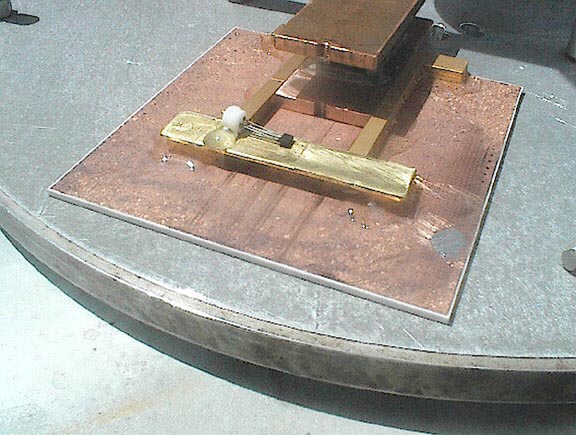
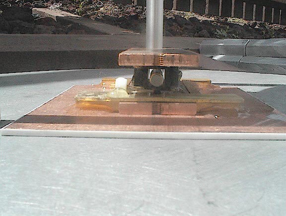
000529-015a
This view shows the mechanical parts of the adjustable diamagnetic
graphite plate with its Hall sensor. Here the parts were simply glued
onto the copper coated alumina plate, and after drying, they were further
epoxied to insure
the parts staying thereon. The wires are not attached to the
Hall sensor socket in this view.

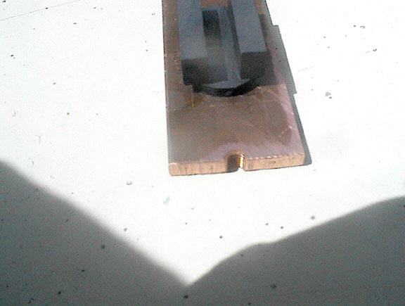
000529-016a
A closer view of the Hall sensor. For illustration the black
Radio Shack neodymium "pill" magnet is roughly centered over the Hall sensor
where it would need to be for a signal. Normally the graphite assembly
is around the levitated magnet.
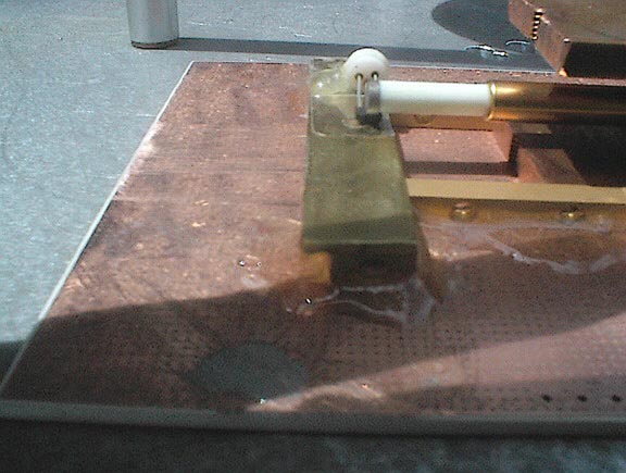
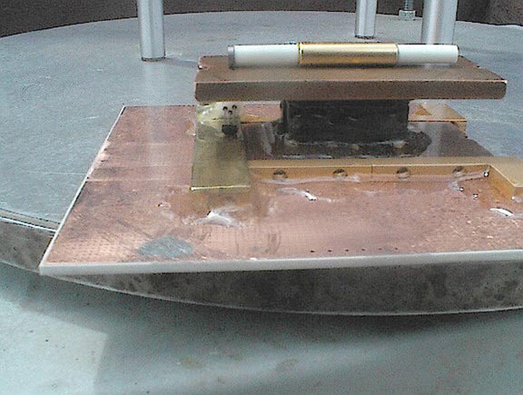
000529-018a
A side view. For the actual seismometer the Hall leads were
bent upward to where the Hall is positioned on the side of the levitated
magnet, rather than underneath. It was felt that the side position
would be less subject to vertical movement readings, and temperature position
changes over time.
The original model idea for this tiltmeter/seismometer.
This comes from U.S. patent 3831287, originally a borehole tiltmeter
made by the Arthur D. Little, Inc., of Cambridge, Ma. The inventors
were Richard M. Sawdo and Ivan Simon. This model was constructed
by using a strong magnetic field (probably Alnico magnets), and levitating
a very lightweight hollow tube of strong diamagnetic graphite. For all
purposes the graphite was tightly constrained within a linear magnetic
field, and used a "flag", optical output and electromagnetic feedback to
maintain the graphite centered in its range. For a homebrew replica
this design is not practical. Temperature problems also plagued this
instrument, and very few were made. This model depended on using
electronic means to center the levitated graphite.
See: IBM Intellectual Property
Network
This homebrew model basically draws from some of the same rough reversed
features of the A.D. Little tiltmeter. The graphite "sandwich" along
with the earths gravity and an overhead magnets are the main parts for
this experimental instrument. For this first model, no
electromagnetic influence is used, it solely depends on the magnetic pendulum
effect coming from the overhead magnets, and it also has no temperature
compensation arrangement; the instrument is simply enclosed in a somewhat
thermally insulated box resting on a concrete pier on loose soil under
a house.
The graphite discs used.
The main specific graphite used, comes from the Model PGV diamagnetic
levitators made at the UCLA Dept of Physics and Astronomy, by Martin Simon.
As of 3/1/2000 the U.S. price is $69.00 each. Simply put, they represent
the most diamagnetic graphite known at this time. Moreover, the item
is sold as non-profit. Its possible to actually use this original
levitator as is for this experiment, but I elected for a sturdier frame
of my own. Outside of this item, a great variety of graphite exists,
but it also can vary greatly in its diamagnetic property, and some is even
magnetic (paramagnetic), and nothing approaches its diamagnetic value.
I've obtained a fair variety of graphite from a number of sources, but,
none have been near as diamagnetic as this material. "Model PGV uses
a more expensive pyrolytic graphite which has the highest diamagnetic susceptiblity
for any solid substance (except superconductors) of about 450 x 10>(-6)",
according to the reference below:
000529-001a
The above view is a part of the initial construction. The
salvaged disks are laid side to side atop the copper plate.
On the sides is the cut up "wedges", used to center the levitated
magnet.

00529-002a
Here the top disks have been added. This completes the graphite
encirclement of the design for the levitated magnet.
000529-003a
Here, epoxy has been used to strengthen and hold the graphite attached
to the bottom plate.

000529-019a
The completed graphite containment of the levitated magnet.
Here another copper plate has been glued to the top.
SEE:
DIAMAGNETIC LEVITATORS FOR SALE
The specific manufacturer of this graphite is Mineral Technologies
Inc. They actually make two varietys of pyrolytic graphite, however,
unfortunately, the company can not identify which variety is the most diamagnetic.
This is in no means unusual; no graphite company makes their graphite
specifically for diamagnetics and therefore their is no real interest on
their part to evaluate their own graphite in this regard. However
in the
sense of using density as a measurement of purity, their SN is slightly
denser being at 2.22 g/cc, (Metric units) while their CN graphite is listed
at 2.19 (which appears to be the graphite of choice) . Some writers
cast the theoretical limit of graphite purity at ~2.25. Further,
actual manufacturing variations, may make these values rather useless,
i.e., thickness, impurities etc; and of course no amateur experimenter
is going to have a diamagnetic measurement machine on hand (k$).
Going further into the specific graphite discs, the gas disposition pyrolytic
graphite is layered on top and bottom (impervious), and the usefull graphite
inbetween is pervious (it can absorb liquids). For some more details
visit the web page, but, the pictures there only show the best example
of pyrolytic surface (there are occasional outgassing pits, in the actual
material)...not the actual cross section of the complete material as actually
sold .
SEE: MINERAL TECHNOLOGIES
INC.
A part of the problem of adopting graphite with a specific levitated
magnet is matching or making the graphite fit the dimensions of the magnet
used, with the necessary diamagnetic spacing. In this case, the graphite
discs are .7" in diameter (two joined side to side and a total of 4 discs
per machine) and the magnet is slightly smaller at some 1" in length.
Its adequate with overlap of the graphite. As I only have a variety
of saws and a old drill press, one can only do with what they have.

000529-004a
This is a view of the parts underneath the overhead ferrite magnets.
Here the levitated magnet is inserted, and
physical moved to center the hall over the Hall sensor center.

000529-006a
Another view with the levitated magnet over the Hall. Here
the levitated magnet uses a prior shorter spacer, which was too short to
allow more signal due to the levitated magnets field being much stronger
than the R.S. magnet.
000529-010a
Another view of the levitated magnet. The copper plates were
chosen primarily for their ability to dampen the levitated magnet.
The copper is actually electrical buss bars from a surplus source.
Unfortunately, the copper
can not be adjusted for less damping as they are glued down.

000529-012a
This view shows the graphite/copper containment block, and the slide
channel guides for adjustments in one direction on the plate. The
alumina plate has copper on both sides, but the not shown bottom has a
circuit layout for a unknown application. The alumina seems to conduct
thermal heat very well; perhaps somewhat of a aid to environmental temperature
changes over time.
The levitated magnet specifics.
Here, the specific magnet is from Forcefield/Wondermagnet.
This unit is some 1" in length by .250" in diameter. The unique polarization
is through half the diameter lengthwise. The polarization means the
magnet floats on its side, however their doesn't seem to be any less significant
gap space from this, and indeed it could almost appear to have a slightly
increased gap space when compared to a normal neodymium rod magnet.
The plating is of a thin gold over perhaps copper or nickel.
This specific magnet is indeed better in its magnetic property, it was
made to order by Dan Bartmann, and fortunately its specific grade is some
1-2 thousand gauss stronger than a normal magnet of its size. Although
somewhat frail compared to other neodymium magnets, its increased gauss
(13,700, or R45) contributes very significantly in its levitation stability
over similar but lesser magnetic neodymium magnets. The web site
to view or order this magnet is below.

000529-013a
This is a view of the main levitated magnet. Attached to both
ends are lightweight plastic tubes. On the left is the
Radio Shack "pill" magnet which is actually centered over the Hall.
The right hand spacer is used to contain a
counterweight to maintain a level balance. The actual instrument
just used solder wire stuffed in the end and
glued in place after the balance is achieved.
000529-021a
The above view simply shows the levitated magnet assembly atop the
copper and graphite containment assembly.
Note the magnet is shorter in length than the graphite; this simply
allows room for the levitated magnet to move a
distance with any seismic signals, and it also provides more diamagnetic
support in case the movement goes the
distance either way. The gold colored aluminum bracks (4),
are simply arranged to act as a guide for movement
adjustments. The inside of the guide was not epoxied down
of course, to allow free movement.
SEE: FORCEFIELD/WONDERMAGNET.COM
Additions to the levitated magnet
While the levitated magnet alone could have been somewhat sufficient
to enable some Hall sensor readings from
seismic activity, the best method of using the Hall sensors involved,
involves placing the sensor nearest the poles
separation area for the strongest gauss field differential.
The present orientation of the rod neodymium does not
allow any method of doing this, except, to a minor degree near the
edge of the magnet where the gauss field is
sharply dispersed. This first model does use acouple
of added hollow plastic spacers which are ~.640" in length by .185" in
diameter, with a wall thickness of .030". The specific
plastic variety is unknown, but it appears lightweight. On the open
end near the Hall sensor was attached a Radio Shack "pill" neodymium magnet.
Now, the orientation and pole separation area allow a more sensitive area
for the Hall sensor use. The spacer simply allows a margin of distance
from the main levitated magnet, so that the Hall predominately is most
sensitive to the Radio Shack magnet and not the main levitated magnet;
although it does have some influence. Again, the instrument
is adjusted to be over the centered thickness (pole division) of the Radio
Shack magnet.
In many ways, this aspect of adding attachments to the levitated
magnet is the most difficult mechanical aspect. If
the base of the instrument is level, the individual gauss length
variation of the levitated magnet can show varying angles of flotation,
other than also being horizontally level. Normally the levitation
magnet is checked for which end has the highest elevation, and this end
has the Radio Shack magnet attached on the end of the spacer. After
checking the level with the parts added, its normal for the opposite end
to have the highest elevation. Here, within the tube is added some
weight to balance the assembly, but it can involve alot of repeated tests,
to achieve a more true level floatation. I used simply insertions
of electronic solder "wire", and either added or reduced the amount.
I didn't use another Radio Shack magnet on the other end, as it only does
more repelling from its magnetic field and isn't as convenient to add or
reduce weight, if two "pill" magnets were used. A added big aspect
of adding parts to the levitated magnet is that this does increase both
the amount of weight the levitated magnet can accomodate and its potential
for increased temperature response. Hence, the spacers and end magnet
were chosen from among many items. The glue used was a "extra strength"
cyanoacrylate, with a setting time of roughly 20-45 seconds. The
glue bottle has the appearance of a blackish tint as opposed to the more
normal clear cyanoacrylate containers of lesser strength, and in varying
faster setting times. Prior cleaning of the surfaces with alcohol,
may, help attachment strength. A small amount of holding compression
till the glue sets up is necessary.
The Graphite Channel Wedges.
The graphite used here is simply to contain the levitated magnet
within its assigned channel of horizontal directional preference.
However, it also is cut to a specific height, which has been demonstrated
to be ideal for this specific levitated magnet and that magnetic gap force
from the overhead ferrite magnets on the discs used. Normally a number
of brass adjustment screws and plates configuration could also be used
to expand or close the gaps. Overall, it has it multiple
purposes, and is very important, although its not a rare item to adapt
for use. This sawed up diamagnetic graphite is from McMaster-Carr,
1/4" by 6"X6" plate which appears to be slightly better than pure
bismuth, and can only roughly be assigned a estimated value of ~ -190.
This guessed value is based on text book references of bismuth (presumed
pure), of ~ -170. The rectangular wedges are 1/4" thick by .450"
length by .345" height; which yields a gap/s of .0475" (+ - .001") on each
side of the top and bottom main discs. In real escence, about any
diamagnetic material from any source could be utilized here, where its
known to be effective. Probably the best material for
the wedges would have been graphite of the same diamagnetic strength as
the upper and lower layers disks; this would have helped limited any sideways
or non-channel movement more.
The Natural Period of the diamagnetic pendulum
The natural period is mostly determined from the distance between
the center of the overhead magnet assembly and the center of the levitated
neodymium magnet. While a rough distance can be measured for a specific
levitated
magnet; another one can have a different length due to the difference
in its gauss strength variations. Generally the period is close to
.9 second in the undamped state, with the distances involved roughly averaging
some 5.725", with a variety of same specific manufactured neodymium magnets.
If the reader trys a variety of magnets, the distance can vary a great
deal, and thus the period will also change in this distance relationship.
I chose the ferrite
magnets approach as the distance was larger, and this increased
the natural period of the instrument.
Temperature Control
Actually there is no electronic temperature control used in this
instrument. The diamagnetic discs used were so strong, that even
with temperature variations of ~10 degrees, the levitated magnet was only
slightly affected, perhaps only rising or lowering some 20 thousands of
an inch in its two gap/s of normally some .0475"per each gap. The
Hall sensor is very sensitive to distance changes, but no temperature control
is used here at this time. Here the instrument is wind shielded and
enclosed in a area with some insulating material, but it is not really
considered ideal. In contrast; if bismuth were used, a temperature
control mechanism would need to be utilized, as with
only afew degrees, the levitated magnet would likely be touching
the upper or lower diamagnetic plates.
Nondesireable effects
Perhaps the most noteable undesired response of this model is that
while the orientation of the levitated magnet
is mostly directional, being as it is somewhat guided, there is
still a side directional responce to seismic influence
which shows up with the Hall sensor. Even if the side wedges
were of the same diamagnetic material, there would
be some lesser lateral response. Ideally the magnet should
probably be contained within a solid mass of the
ideal diamagnetic material, in the form of a hole, where the diamagnetic
graphite influence would exert its most force to limit lateral or side
movement, but the cost would then be extremely high. Alternatively,
a square shaped
neodymium magnet within a proper sized square containment should
have less response to lateral movement, but
it won't be eliminated entirely. Obviously a different sensor
using for example light, would be much less sensitive
to the lateral movement, if the orientation is correct; but it will
probably involve magnetic problems with the light
and receiver devices themselves.
With the mass being a magnet; obviously the magnetic effects from
moving bus's and vehicles creates a effect on the levitated magnet.
Normally seismometers use non-magnetic masses. I suspect shielding
might help somewhat but
it may prove to be very difficult to do, as the shield itself needs
some distance away from the levitated magnet, to not be drawn toward the
shielding.
First Trial operation using a damped levitated magnet
with a Hall Sensor
Here the first trial was started on 5/16/2000, using the same Hall
sensor circuit as used with the S-G seismometer
previously. Only one Hall is used at one end. Its also
possible to use more, but adjustments can be much tougher to match responses.
The sensitivity is greatly reduced from the S-G setup, as it simply senses
the magnet coming toward or away from the sensor, rather than the larger
4 pole junction magnet used in that setup. My best estimate, is that
it could respond to the stronger motion aspects of larger earthquakes,
and perhaps near by quakes of sufficient magnitude. For the
initial test, the diamagnetic seismometer was simply placed on a large
wood shelf in a room within the house, and it seemed to respond well.
Thereafter it was placed in my main vault alongside
another seismometer. Initial results seemed somewhat
different than expected, it does respond to large city bus
passings (approximately 80 feet away), but smaller vehicles don't
seem to affect it much, if at all. Most noted,
is that for low level microseisms, the comparison to a regular coil-magnet,
do not show any realistic match. Tilt
affects do seem to be much more comparable though. Relatively
close lightning strikes, do generate a short "spike", on the machine, but
that could also be induced from the power line. It seems to respond
to wind pressures on the houses external area, however this could be a
air pressure induced effect. I expect problems with the
levitated mass in its susceptibility to some sideways movement in
its channel and subsequent contact with the
graphite and or Hall sensor, if any passing quake waves have sufficient
magnitude. As of 5/16/2000, the only
noted oddity thus far, has been noted that there are "trains" of
from 5-10 second waves from time to time,
that don't have any match in the other seismometers outputs.
For this effect, I have no present explanation. There is a train
line some 1/2 mile away, but that is not the cause, nor does it affect
the mass at that distance. Too add to this report, the mass seems
to be overdamped from the eddy current effects of the plates of copper
close by; and
there is no current way to change that aspect, in this specific
design as its all glued together. Another noted effect,
is that while norml lawn mowing activities, induce some tilt effect
in a normal seismic coil/magnet unit; the tilt with
the diamagnetic seismic seems to be roughly twice the amount of
amplitude...this is likely a combined tilt and
electromagnetic effect from the gas engine on the mower, but the
recording is a fair match overall.
Overall, its been a real challenge to gather the right materials.
However, with the instrument in operation all the
past struggles seem to have been worth the opportunity to watch
what it does and possibly gather more information for a newer and better
designed model possibly in the future.
ON TO SOME QUAKE RECORDS WITH THE DIAMAGNETIC
SEISMOMETER
RETURN TO THE INDEX