Alexander Technical Center
Week of Dec 1, 2003
Many thanks to Jake, George and Mike
As we went along we would drill out the holes to the correct size to accept the rivets specified for that particular hole.
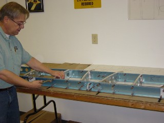
Here is the Horizontal Stabilizer Spars and Ribs being put together.
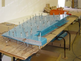
The next steps were to disassemble the pieces. Then the fun started. We deburred all the holes we drilled, scuffed the interior parts that will be primed, then either countersunk or dimpled the holes as required to accommodate flush rivets.
The pieces then went to the paint shop to be primed.

Here is the rear spar for the Horizontal Stabilizer. Note the new color from the primer, and the rivets now holding the spar to the doubler behind it.

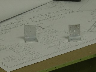
This open section is where it will attach to the fuselage. You can see the attach brackets made earlier, now primed and riveted to the front spar.
Also note the flush rivets on the skins. The blue plastic you see on the outside of the skins is temporary, and help to keep the skins from being scratched while being worked on. The plastic had to be removed for the areas that were to be riveted.
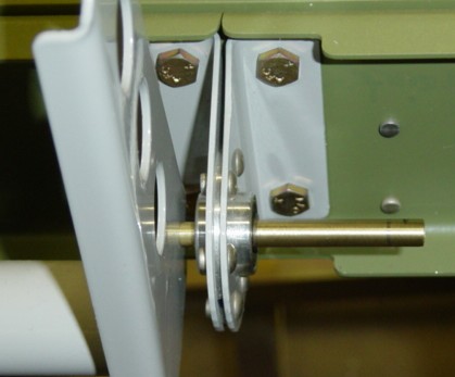
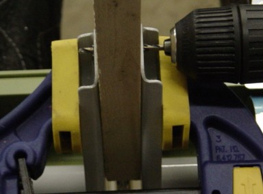
The first hole was drilled at a specified location per the plans, the a drill guide was made by drilling a straight hole through a wooded block with a drill press. Both elevator counterweight arms are aligned with the horizontal stabilizer. Then the wood block is used as a guide to drill straight through to the other control horn.