
TECHNOLOGY SCAN ON INTEGRATED GASIFICATION COMBINED CYCLE (IGCC)
1.0 COAL GASIFICATION & IGCC
1.1 Coal Gasification
Coal gasification is a process that converts coal from a solid to a gaseous fuel through partial oxidation. Once the fuel is in the gaseous state, undesirable substances, such as sulfur compounds and coal ash, may be removed from the gas by established techniques. The net result is a clean, transportable gaseous energy source.
In contrast to combustion process which works with excess air, gasification process works on partial combustion of coal with the oxygen supply controlled (generally 20 to 70% of the amount of O2 theoretically required for complete combustion) such that both heat and a new gaseous fuel are produced as the coal is consumed.
C + 1/2 O2 gasificationà CO
C + H2O gasificationà CO + H2
1.2 IGCC (Integrated Gasification Combined Cycle)
The IGCC process is a two-stage combustion with cleanup between the stages. The first stage employs the gasifier where partial oxidation of the solid/liquid fuel occurs by limiting the oxidant supply. The second stage utilizes the gas turbine combustor to complete the combustion thus optimizing the gas turbine/combined cycle (GT/CC) technology with various gasification systems. The SynGas produced by the Gasifiers however, needs to be cleaned to remove the particulate, as well as wash away sulphur compounds and NOx compounds before it is used in the Gas Turbine. It is the Integration of the entire system components which is extremely important in an IGCC Plant.
Various sub-systems of an IGCC Plant thus are:
i) Gasification Plant
ii) Power Block
iii) Gas Clean-up System
2.0 Relative Merits of IGCC over Conventional PC Fired Technology
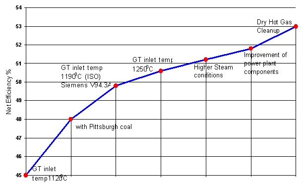
Recent advances in the Gas Turbine technologies have presented great potential towards much higher gas turbine efficiencies. Increasing the firing temperatures and utilizing materials that withstand higher temperatures can increase the efficiency of gas turbine. Continuous developments have been taking place in the newer materials of construction thus consequent higher gas turbine performance. At present the efficiency of gas turbines is in the range of 45-50% which is projected to go upto 60% with the development of H-technology by GE. The advances in gas turbines would improve the overall efficiency of IGCC plant.
EXPECTED IMPROVEMENTS OF IGCC POWER PLANT EFFICIENCY
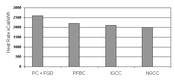
The heat rates of the plants based on IGCC technology are projected to be around 2100 kCal/kWh compared to the heat rates values of around 2500 kCal/kWh for the conventional PC fired plants.
IGCC technology has been proven for a variety of fuels, particularly heavy oils, heavy oil residues, petcokes, and bituminous coals in different parts of the globe. In fact the same gasifiers can handle different types of fuels.
IGCC is an environmentally benign technology. The emission levels in terms of NOx, SOx and particulate from an IGCC plant have been demonstrated to be much lower when compared to the emission levels from a conventional PC fired steam plant. In fact, no additional equipment is required to meet the environment standards.
3.0 Type of Gasifiers
The Coal Gasification requires the presence of an oxidant in the process. Air or Oxygen may be used as an oxidant and the gasifiers are accordingly known as either Air-Blown or Oxygen-Blown Gasifiers.
Typical operating characteristics of the gasifiers are as follows:
|
Moving Bed |
Fluidised Bed |
Entrained Bed |
|
|
Exit Gas Temp. 0C |
420 - 650 |
920 - 1050 |
1200 |
|
Coal Feed size |
< 50 mm |
< 6 mm |
< 100 mesh |
|
Ash Conditions |
Dry / Slagging |
Dry / Agglomerating |
Slagging |
4.0 Technology Suppliers:
Different technology suppliers worldwide have developed the gasifiers which are either air-blown or oxygen-blown and are either of the moving bed, entrained bed or fluidised bed. The choice of the type of the gasifier is purely a factor of the coal/fuel characteristics. Various technology suppliers for the gasification process are as below:
|
Technology Supplier |
Coal Feed Type |
Oxidant |
Gasifier Type |
|
Texaco, USA / |
Water Slurry |
O2 |
Entrained Flow |
|
Shell, USA |
N2 carrier/Dry |
O2 |
Entrained Flow |
|
KRW, USA |
Dry |
Air |
Fluidised Bed |
|
Lurgi, Germany |
Dry |
Air |
Fluidised Bed |
|
British Gas/ Lurgi |
Dry |
O2 |
Moving Bed |
|
Prenflo, USA / Krupp Uhde , Germany; Deutsche-Babcock, Germany |
Dry |
O2 |
Entrained Flow |
|
Destec Energy, USA |
Water Slurry |
O2 |
Entrained Flow |
|
IGT U-Gas, USA / Carbona, Finland; IBIL, India |
Dry |
Air |
Fluidised Bed |
|
Rheinbraun HTW, Germany RWE Energie, Germany |
Dry |
Air |
Fluidised Bed |
|
MHI, Japan / IGC, Japan |
Dry |
Air/O2 |
Entrained Flow |
|
ABB-CE, USA |
Dry |
O2 |
Entrained Flow |
|
VEW/Steinmuller, Germany |
O2 |
Entrained Flow |
|
|
Hitachi |
Dry |
O2 |
Entrained Flow |
|
Noell/GSP |
Dry |
O2 |
Entrained Flow |
|
Ahlstrom, Sweden |
Dry |
Air |
Fluidised Bed |
5.0 SynGas Characteristics
Composition of the syngas depends on the fuel as well as on the gasification process. The typical characteristics of the SynGas as generated from different fuels at some of the IGCC projects are presented below.
|
Project |
|||||||
|
PSI Wabash |
Tampa Polk |
El Dorado |
Shell Pernis |
Sierra Pacific |
IBIL |
Schwarze Pumpe |
|
|
Fuel |
Coal |
Coal |
Pet Coke/ Waste Oil |
Vacuum Residue |
Coal |
Lignite |
* |
|
H |
24.8 |
27.0 |
35.4 |
34.4 |
14.5 |
12.7 |
61.9 |
|
CO |
39.5 |
35.6 |
45.0 |
35.1 |
23.5 |
15.3 |
26.2 |
|
CH4 |
1.5 |
0.1 |
0.0 |
0.3 |
1.3 |
3.4 |
6.9 |
|
CO2 |
9.3 |
12.6 |
17.1 |
30.0 |
5.6 |
11.1 |
2.8 |
|
N2+Air |
2.3 |
6.8 |
2.1 |
0.2 |
49.3 |
46.0 |
1.8 |
|
H2O |
22.7 |
18.7 |
0.4 |
-- |
5.7 |
11.5 |
-- |
|
LHV, KJ/M3 |
8350 |
7960 |
9535 |
8235 |
5000 |
4530 |
12500 |
|
Tfuel, oC |
300 |
371 |
121 |
98 |
538 |
549 |
38 |
|
Oxidant |
O2 |
O2 |
O2 |
O2 |
Air |
Air |
O2 |
* Lignite/Oil Slurry with Waste Plastic & Waste Oil
6.0 Gas Clean-up System
The typical steps for Gas Clean-up System aim at particulate removal, sulfur removal and NOx removal. This is achieved as follows:
Hot Gas Clean-Up technology is currently under demonstration phase and various demonstrations have not been successful so far. Wet scrubbing technology, though with a lower efficiency, still remains the preferred option for gas clean-up systems in IGCC.
Technology Suppliers for Particulate Removal
|
S. No |
Manufacturer |
Gas Temp. (Max.) |
Particle collection efficiency |
Remarks |
|
1. |
Westinghouse Ceramic Candle Filter |
10000C |
99.99% for 0.1 mm size |
Hanging Type Candles |
|
2. |
LLB Lurgi Lentjes Babcock Ceramic Candles Filter |
10000C |
99.99% |
Supported both sides |
|
3. |
Pall Process Filtration Ceramic Candle Filter |
10000C (max.) |
99.99% |
Supported both sides; Clay bonded silicon carbide filter |
|
4. |
Schumacher Ceramic Candle Filter |
10000C |
99.9% |
Hanging type candles; Clay bonded silicon carbide filter |
|
5. |
Mott Metal Candle Filter |
9500C |
99.99% |
Hanging type candles; Sintered Hastelloy |
6.2 Sulfur Removal
Sulfur from the hot fuel gas is captured by reducing it to H2S, COS, CS2 etc. The current sulfur removal systems employ zinc based regenerative sorbents (zinc ferrite, zinc titanate etc.) Such zinc based sorbents have been demonstrated at temperatures upto 650 0C.
Sulfur is also removed by addition of limestone in the gasifier. This is commonly adopted in air-blown fluidised bed gasifiers.
In fact, in the case of Air Blown Gasifiers, sulfur is captured in the gasifier bed itself (above 90%) because of addition of limestone. The sulfur captured in the bed is removed with ash.
7.0 Power Block
The Power Block in the IGCC Plant is essentially a Gas Turbine Unit that operates on SynGas. This Gas Turbine Unit is basically the same as used for Natural Gas with certain modifications. The areas that are modified and also which need to be critically evaluated for use with SynGas are:
The gas turbine combined cycle technology has been proven for use with natural gas as well as with syngas.
8.0 Status of IGCC Technology
The technology level for each individual system component of IGCC i.e. gasification block, gas clean-up system and power block have already been established and proven in practice at commercial level. Integrating these individual technologies for the electricity generation is the concept of IGCC. To demonstrate IGCC technology at the commercial level, a number of projects have been in demonstration/operation stage. The fact that the IGCC technology has reached maturity stage, can be seen from the following table which gives status of various IGCC projects.
Major (Coal based) IGCC Projects Worldwide -- under operation
|
Project |
Capacity |
Operation |
Fuel |
Remarks |
|
Luenen, STEAG, Germany |
170 MW |
Operated 1972-77 |
Oil |
First Commercial Scale Gasifier (5 Lurgi dry ash gasifiers, Siemens KWU combined cycle) |
|
Coolwater Plant, Barstow,California, USA |
125 MW |
Operated 1984-88 |
Coal |
Texaco Gasifier (1000TPD) |
|
Plaquemine Plant, Louisiana,USA |
160 MW |
In operation since April,1987 |
Coal |
Dow (Destec)Gasifier(2200TPD) |
|
Demkolec Buggenum Plant, Netherlands |
253 MW |
Started operation in 1993, commercial w.e.f. 1.1.98 |
Coal |
Shell Gasifier � Initial problems encountered in Gas Clean-up System. Now operating with good availability. |
|
PSI Energy, Wabash River Plant, USA |
262 MW |
Commissioned November,1995 |
Coal |
Destec Gasifier, Repowering plant |
|
Tampa Electric Polk Power Plant, USA |
260 MW |
Commissioned Sep. 1996 |
Coal |
Texaco Gasifier |
|
Sierra Pacific Pinon Pine Plant, USA |
100 MW |
Commissioned 1998 |
Coal |
KRW Gasifier |
|
ELCOGAS, Puertollano, Spain |
335 MW |
Prenflow, Krupp Uhde |
Coal |
Prenflo gasifier commissioned in 1998 |
|
Schwarze Pumpe, Germany |
40 MW |
Noell KRC (7 fixed bed gasifiers) |
Coal/ Wastes |
commissioned on syngas September,1996 Power/methanol |
Major (Refinery Residue based) IGCC Projects World-wide --- Under Operation
|
Project |
Capacity |
Gasifier |
Fuel |
Status |
|
Texaco El Dorado, USA |
40 MW + Steam |
Texaco |
Waste/ Pet Coke |
Commissioned September, 1996 |
|
ILVA, Taronto, Italy |
500 MW |
-------- |
mill recovery gases |
Commissioned January,1997 |
|
Shell PER+, Pernis, Netherlands (IGCC retrofit) |
127 MW |
Shell SGHP process |
Heavy residues |
Commissioned on NG in June,1997 & on syngas at November,1997 |
|
ISAB, Sicily, Italy |
520 MW |
Texaco |
Asphalt |
Commd. late 1999 (2 Siemens V94.2) |
|
Sarlux, Sardinia, Italy |
551 MW |
Texaco |
Refinery Residue |
Commd. Early 2000 (3 GE MS9001E GTs) |
|
API-Energia, Falconara, Italy |
280 MW |
Texaco |
Refinery Residue |
2000 (ABB GT13E2 GT) |
|
Star, Delaware, USA Saudi Aramco-Texaco JV |
240 MW |
Texaco |
Pet Coke |
Commd. August 2000 , Cogen (120MWe + steam), Repowering, 2 X GE 6FA GTs |
Status of IGCC Projects World-wide --- Under Construction
|
Project |
Capacity |
Gasifier |
Fuel |
Commissioning |
|
KoBra, Kraftwerk Goldenberg, Hurth, Germany |
312 MW |
HTW/ Rheinbraun AG |
Coal |
2001 |
|
AGIP Petroli, Italy |
250 MW |
Refinery residue |
2002 Power/Steam/H2 |
|
|
Fife Energy, Scotland |
109 MW |
British Gas/Lurgi |
Wastes/pet coke/ coal |
2001 Global Energy, $117m |
|
EXXON, Baytown, USA |
40 MW |
Texaco |
Pet Coke |
1999 Power/ H2/ CO |
|
General Seikyu K.K., Kawasaki, Japan |
540 MW |
Texaco |
Heavy oil |
2001 |
|
Vresova, Czech Republic |
400 MW |
HTW |
Coal |
--- |
|
IBIL,Gujarat, India |
53 MW |
Carbona/ Enviropower |
Lignite |
Environment approval pending |
Gasification Technology Demonstration/Pilot Scale Plants
|
SCGP-1, Shell Oil Deer Park Complex, Texas, USA. |
250 TPD demonstration unit |
Operated between 1987-1991 |
Coal/lignite/pet coke |
Shell Gasifier - 80% coal to clean gas efficiency, 99% sulfur removal achieved. Gas used for synthesis. |
|
Rheinische Braunkohlenwerke, Berrenrath, Germany |
720 TPD |
Dry Lignite |
HTW Gasifier; gas used for methanol production |
|
|
American Natural Gas Co. Beaulah, North Dakota, USA |
1000 TPD |
In operation since 1984 |
Lignite |
14 Lurgi dry ash gasifiers of 1000 TPD each for syngas production |
|
British Gas Lurgi Westfield, Scotland |
600 TPD/ 30MWe |
Commissioned in 1984 |
Demonstration unit; pressurised dry feed moving bed slagging BGL Gasifier |
|
|
IGT U-Gas Shanghai, China |
800 TPD (8 trains) |
Commissioned in Dec,1994 |
Coal |
1st IGT U-Gas commercial plant Industrial fuel gas |
|
Krupp-Koppers Saarbrucken, Germany |
48 TPD |
Coal |
||
|
IGT RENUGAS Maui, Hawaii, USA |
Commissioned in October,1996 |
Bagasse |
IGT Biomass gasification technology demonstration plant |
|
|
Sydkraft, Varnamo, Sweden |
6 MWe + 9MWth |
in operation since June,1996 |
biofuel |
Pilot Plant; Ahlstrom CFB Gasifier, Sydkraft & Foster Wheeler JV |
From the above, it can be seen that IGCC technology has now reached commercialization stage in the USA & Europe with a number of plants already in demonstration/operation phase. It may be noted that a number of IGCC based plants have been set up in USA with financial participation of USDOE with the objective of promoting the Clean Fuel Technology as well as part funding of the high cost of such plants.
A Japanese R&D team at the Tokyo Institute of Technology has claimed to have developed a new hot air-blown gasification system suitable for all kinds of solid fuel ranging from coal to waste. A demonstration plant of 4tpd capacity using this technology is scheduled for completion by 2000. The process named MEET (Multi-stage Enthalpy Extraction Technology) system, using air at 1000
0C is being developed to suit Indian fuels.9.0 Operational feedback
Typical problems that have been encountered in various projects relate to the following areas:
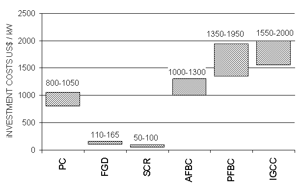
10.0 Investment Costs
The costs for the IGCC based plants as reported are noted to be somewhat variable, depending on economy of scale, local labor costs, and applicable engineering standards. Further, gasification costs usually are estimated in combination with the downstream processing equipment necessary for delivery of a syngas suitable for conversion to the designed end product. Accordingly, gasification investment costs are best addressed on a project specific basis. The typical project costs as reported for different demonstration/commercial projects are as below:
|
S.S.No |
Project |
Capacity |
Fuel |
Gasifier Type |
Gasifier Supplier |
CapitalCost $/kW |
|
1. |
Buggenum, Demkolec, Netherlands |
253 MW |
Coal |
O2 blown |
Shell |
2400 |
|
2. |
Polk, Tampa Electric, USA |
260 MW |
Coal |
O2 blown |
Texaco |
2000 |
|
3. |
Wabash, PSI Energy Inc. USA |
262 MW |
Coal |
O2 blown |
Destec/Dow |
1600 * |
|
Texaco El Dorado, USA |
35 MW |
Residue |
O2 blown |
Texaco |
2150 |
|
|
4. |
Pinon Pine, USA |
100 MW |
Coal |
Air Blown |
KRW |
2320 |
|
5. |
Puertollano, Spain |
335 MW |
Coal |
O2 blown |
Prenflo |
2900 |
|
6. |
API-Energie, Italy |
280 MW |
Residue |
O2 blown |
Texaco |
2850 |
|
7. |
SARAS - Sarlux, Italy |
550 MW |
Residue |
O2 blown |
Texaco |
2100 |
|
8. |
ISAB Energy, Italy |
512 MW |
Residue |
O2 blown |
Texaco |
2400 |
Source: Data published in journals
(*) Wabash river is a repowering IGCC.
An IGCC plant operating on heavy oil is somewhat less complex than a coal-based IGCC and costs are marginally less. The following graph compares current investment costs of IGCC with other new technologies.
Comparison of IGCC investment costs with other new technologies
Source: World Bank Website, Data published in journals
Source:
BACK TO MY HOME PAGE | IGCC | CFBC | PFBC | SOLAR THERMAL | WIND POWER | GEOTHERMAL | FUEL CELLS | COALBED METHANE