Overview
Microcontroller
External Memory
Liquid Crystal Display (LCD)
Temperature Sensor
Software
Study Result
1. Overview
The overall picture of the system is shown
in figure 1. It basically consists of four parts: external memory, LCD
display, temperature sensors and RS232 connection to external computer
for setting and monitoring. Each subcomponents will be discussed in great
details on the following section. Since Atmel MEGA 103L on the STK300 development
board has the capability on handling on-chip real time clock, the external
real time clock for this project is not necessary, eventhough the requirement
of external RTC is crucial for industrial datalogger. The details of it
will be discussed on the Future section.
Basic Diagram of Temperature Logger
(Click to Enlarge)
2. Microcontroller
The system will be based on ATMEL STK300 prototype development board. This board is selected to expedite the development of the system, since all the peripherals are already in place, including the sockets for external RAM and latch. This board also includes the RS232 connection, for data downloading.
The STK300 megaAVR Starter Kit is a complete evaluation platform for taking MegaAVR design from conception to realization. The STK300 megaAVR Starter Kit is the ideal method for getting started with these high-performance, low-power RISC microcontrollers. The development board comes complete with push-button switches, LEDs, and RS-232 Port. All ports of the megaAVR controller is accessible through header connectors on the edge of the board. There is also a 14-pin header for connection to an off-board liquid crystal display (LCD), with built-in contrast adjustment. The board has support for external data memory with sockets for SRAM and address latch devices, plus a header connector for external memory mapped devices. The internal 10 bits A/D converter on the megaAVR microcontroller is accessible through a separate header connector on the board. The analog reference voltage can be adjusted with an on-board potentiometer or optionally with an external reference voltage. 3.3V or 5V operation can be selected by a jumper setting on the board.The Starter Kit includes on-board brown-out detection.
The Main Features of STK300
(Click on image to enlarge)
ATMega 103L processor has been used as the microcontroller, with the abovementioned STK300 development board. It has real time clock capacbility with the addition of 32.768kHz external crystal, as an addition to 4 MHz main crystal. The RTC crystal is connected to Timer 0, and with proper scalling, it generates an interrupt at exactly 1 millisecond.
Block Diagram for Mega103L
(Click image to enlarge)
3. External memory
The Hitachi HM62256B, CMOS static RAM will be used to store the collected data. Without the external SRAM, the system can only store 100 measured data, but the number can go up to 2500 measured data with the addition of 32K x 8 SRAM.

Schematics for External SRAM
(Click image to enlarge)
4. Liquid Crystal Display (LCD)
A 16´1 Character LCD has been used to show the current temperature reading and current date and time. The hardware connection for the LCD to microcontroller is shown as follow:
LCD Connections
5. Temperature Sensors
For this project, two kind of temperature sensors have been used: LM34 and LM35. Both are almost the same except the first one is giving out Farenheit reading, while the second one giving out Celcius output. The operation and interface for both devices are almost the same, with the same output accuracy: 10mV/°F and 10mV/°C respectively. The basic connection for temperature sensors is shown as figure below:
For calculation, the following equation has been used to get the number either in degree farenheit or calcius.
ADvalue is 10 bit
ADC result
Following is the description on LM35 (extracted from National Semidconductor Webpage)
The LM35 series are precision integrated-circuit temperature sensors, whose output voltage is linearly proportional to the Celsius (Centigrade) temperature. The LM35 thus has an advantage over linear temperature sensors calibrated in ° Kelvin, as the user is not required to subtract a large constant voltage from its output to obtain convenient Centigrade scaling. The LM35 does not require any external calibration or trimming to provide typical accuracies of ±¼°C at room temperature and ±¾°C over a full -55 to +150°C temperature range. Low cost is assured by trimming and calibration at the wafer level. The LM35's low output impedance, linear output, and precise inherent calibration make interfacing to readout or control circuitry especially easy. It can be used with single power supplies, or with plus and minus supplies. As it draws only 60 µA from its supply, it has very low self-heating, less than 0.1°C in still air. The LM35 is rated to operate over a -55° to +150°C temperature range, while the LM35C is rated for a -40° to +110°C range (-10° with improved accuracy).
Features
- Calibrated directly in ° Celsius (Centigrade)
- Linear + 10.0 mV/°C scale factor
- 0.5°C accuracy guaranteeable (at +25°C)
- Rated for full -55° to +150°C range
- Suitable for remote applications
- Low cost due to wafer-level trimming
- Operates from 4 to 30 volts
- Less than 60 µA current drain
- Low self-heating, 0.08°C in still air
- Nonlinearity only ±¼°C typical
Low impedance output, 0.1 [Ohm] for 1 mA load
Internal Block Diagram for LM35
(Click image to enlarge)
To get the datasheet for temperature sensor, click here
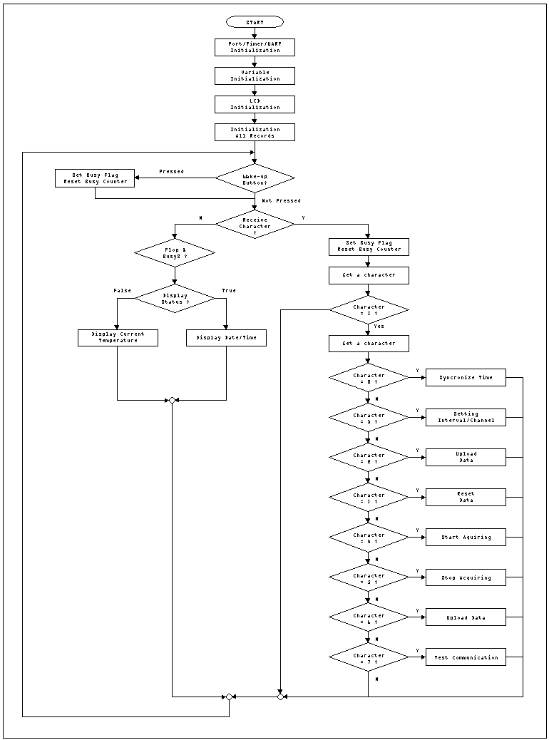
6. Software
The firmware is based on CodeVisionAVR C compiler. The full source code can be found in the Source Code Section. The flow of the main subroutine is shown if figure below.
7. Study Result
Two studies has been carried out by me. The first is to observe the battery life time. A 9V akaline battery was used in this study. The system later was put under stress tess, in which there's no clear LCD operation after 2 minutes of inactive. The results shows that the user can expect the system running exclusively on the battery for almost 17 - 22 hours operation, with assumption that the system will not work at full features for voltage under 5.5V.
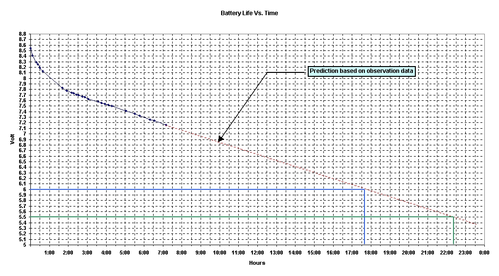
(Click on image to enlarge)
The second study is to monitor the voltage of analog reference. The analog reference uses internal circuitry which is come in STK300 development board. It is observed that the value of analog reference is decrementing over the time. Since we're depending on this value, for accuracy of Analog to Digital Converter (ADC), we have to keep calibrate the analog reference. This can be eliminated by putting a stabil and accurate 3V ot 5V voltage regulator and get the source from main input.The result of this study is shown below
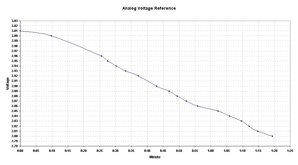
(Click on image to enlarge)