Introduction
This circuit allows you to record audio from a telephone line into a tape recorder or computer soundcard. Most of the parts for this circuit can be scrounged from an old modem, with some work, it is possible to rewire the modem circuitry and use the old modem case.
Note that some countries have laws that require the user of a phone recording device to notify the party on the other end of the line that they are being recorded.
Theory
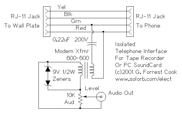
There's not much to this circuit. The two RJ-11 jacks are set up to feed the telephone circuit through from the wall to the phone. The active signal for a single phone is on the red and green wires. Yellow and black are usually used for a second phone line. The 0.22uF capacitor blocks any DC current from flowing through the transformer. The transformer isolates the telephone side of the circuit from the tape recorder side. The zener diodes protect your recorder from the 90 volt ringing signal and other transient spikes. The 10K potentiometer is used to adjust the level to the tape recorder.
Use
Using two RJ-11 phone line jumpers, connect one side of the interface to the wall plate and the other side to a telephone. Connect the audio out to a tape recorder or PC sound card's auxilliary input. Set the recording level and start recording. It should also be possible to inject an audio signal into the audio output jack and have it appear on the phone line, the level control should be all the way up, drive the circuit from an amplifier that is capable of running a small speaker.
Parts
2X RJ-11 phone Jacks
2X 0.22uF 200V capacitor
2X 600 ohm to 600 ohm modem transformer
2X 9V 500mW or 1W zener diodes
1X 10K audio taper potentiometer
1X RCA audio jack
~~~this plan is not mine and i have not tested it or built it~~~