Data Link Layer
The middle Layer in the stack, the Data Link Layer, serves as an intermediate stage between the Transaction Layer and the Physical Layer. The primary responsibilities of the Data Link Layer include Link management and data integrity, including error detection and error correction. The transmission side of the Data Link Layer accepts TLPs assembled by the Transaction Layer, calculates and applies a data protection code and TLP sequence number, and submits them to Physical Layer for transmission across the Link. The receiving Data Link Layer is responsible for checking the integrity of received TLPs and for submitting them to the Transaction Layer for further processing.
1.1 Services Provided By Data Link Layer
• Data Exchange
• Error Detection and Retry
• Initialization and power management services
• Data link layer packets (DLLPs)
1.1.1 Data Exchange
• Accept TLPs for transmission from the Transmit Transaction Layer and convey them to the Transmit Physical Layer
• Accept TLPs received over the Link from the Physical Layer and convey them to the Receive Transaction Layer
Error Detection and Retry
• TLP Sequence Number and LCRC generation
• Transmitted TLP storage for Data Link Layer Retry
• Data integrity checking for TLPs and Data Link Layer Packets (DLLPs)
• Positive and negative acknowledgement DLLPs
• Error indications for error reporting and logging mechanisms
• Link Acknowledgement Timeout replay mechanism
Initialization and power management services
Track Link state and convey active/reset/disconnected state to Transaction Layer.
1.1.4 Data link layer packets (DLLPs)
• DLLPs are used for Link management including TLP acknowledgement, power management, and exchange of Flow Control information.
• DLLPs are used to Transferred between Data Link Layers of the two directly connected components on a Link.
1.2 Transmitter side
• Accept TLPs for transmission from the Transmit Transaction Layer and convey them to the Transmit Physical Layer
• TLP Sequence Number and LCRC generation Transmitted TLP storage for Data Link Layer Retry
Figure: 1 Transmitter Data Link Layer
The Transaction Layer must observe the flow control mechanism before forwarding outbound TLPs to the Data Link Layer.
If sufficient credits exist, a TLP stored within the virtual channel buffer is passed from the Transaction Layer to the Data Link Layer for transmission.
The Data Link Layer is responsible for TLP CRC generation and TLP error checking. For outbound TLPs from transmit Device A, a Link CRC (LCRC) is generated and appended to the TLP. In addition, a sequence ID is appended to the TLP. Device A's Data Link Layer preserves a copy of the TLP in a replay buffer and transmits the TLP to Device B. The Data Link Layer of the remote Device B receives the TLP and checks for CRC errors.
If there is no error, the Data Link Layer of Device B returns an ACK DLLP with a sequence ID to Device A. Device A has confirmation that the TLP has reached Device B (not necessarily the final destination) successfully. Device A clears its replay buffer of the TLP associated with that sequence ID.
If on the other hand a CRC error is detected in the TLP received at the remote Device B, then a NAK DLLP with a sequence ID is returned to Device A. An error has occurred during TLP transmission. Device A's Data Link Layer replays associated TLPs from the replay buffer. The Data Link Layer generates error indications for error reporting and logging mechanisms.
For a given TLP in the replay buffer, if the transmitter device receives a NAK 4 times and the TLP is replayed 3 additional times as a result, then the Data Link Layer logs the error, reports a correctable error, and re-trains the Link
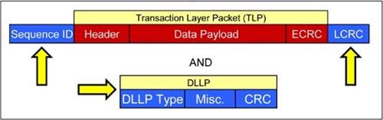
Figure 2: TLP and DLLP structure at Data link layer
1.2.1 Difference between TLP and DLLP
Sno |
DLLPs
|
TLPs |
1. |
It uses 16 bit CRC |
It uses 32 bit LCRC |
2. |
DLLPs are sent point-to-point, between the two components on one Link. |
TLPs are routed from
One Component to another, potentially through one or more intermediate components. |
3. |
Received DLLPs, which fail the CRC check, are discarded. |
TLPs which fail the data integrity checks (LCRC and sequence number), or which are lost in transmission from one component to another, are re-sent by the Transmitter. |
1.2.2 States in Data Link Layer
DL_Inactive : Physical Layer reporting Link is non-operational or nothing is connected to the Port
DL_Init : Physical Layer reporting Link is operational, initialize Flow Control for the default Virtual Channel
DL_Active : Normal operation mode
The format of a TLP with the Sequence Number and LCRC code applied is shown in Figure 3.
Figure: 3
1.2.3 Counters used in LCRC and Sequence Number
12-bit counter
• NEXT_TRANSMIT_SEQ: Stores the packet sequence number applied to TLP. If DL_Inactive state is set, then the stored NEXT_TRANSMIT_SEQ will be0
• ACKD_SEQ: Stores the sequence number acknowledged in the most recently received Ack or Nak DLLP. If DL_Inactive state is set, then the stored ACKD_SEQ will be 1
2-bit counter
• REPLAY_NUM : Counts the number of times the Retry Buffer has been re- transmitted. If DL_Inactive state is set, then the stored REPLAY_NUM will be 0
1.2.4 Sequence number calculation
Figure: 4
Following formula is used to calculate next sequence number
NEXT_TRANSMIT_SEQ:= (NEXT_TRANSMIT_SEQ + 1) mod 4096
If the equation (NEXT_TRANSMIT_SEQ ACKD_SEQ) mod 4096 >= 2048 is true, the Transmitter must cease accepting TLPs from the Transaction Layer until the equation is no longer true
1.2.5 LCRC calculation
The LCRC value is calculated using the following mechanism (see Figure 5)
The following points should be remembered while calculating LCRC.
• The polynomial used has coefficients expressed as 04C1 1DB7h
• The seed value (initial value for LCRC storage registers) is FFFF FFFFh
• The LCRC is calculated using the TLP following sequence number application (see Figure 3)
• LCRC calculation starts with bit 0 of byte 0 (bit 8 of the TLP sequence number) and proceeds from bit 0 to bit 7 of each successive byte.
• Note that LCRC calculation uses all bits of the TLP, regardless of field type, including reserved fields
• The remainder of the LCRC calculation is complemented, and the complemented result bits are mapped into the 32-bit LCRC field as shown in Table 1.
• The 32-bit LCRC field is appended to the TLP following the bytes received from the Transaction Layer (see Figure 3)
Figure: 5 LCRC Calculations
Table: 1 mapping of Bits into LCRC fields
1.2.6 Implemented Specifications
• Receives TLP from the buffer in Transaction layer
• Sequence number is calculated using the above formula and it is appended with received TLP. In 16 bits sequence number last 4 bits are reserved. Reserved bits are set to 1
• LCRC is calculated using a circuit as shown in figure and it is appended at the end of received TLP.
• Receiver side
The receive side of the Data Link Layer is responsible for LCRC error checking on inbound TLPs. If no error is detected, the device schedules an ACK DLLP for transmission back to the remote transmitter device. The receiver strips the TLP of the LCRC field and sequence ID.
If a CRC error is detected, it schedules a NAK to return back to the remote transmitter. The TLP is eliminated.
The receive side of the Data Link Layer also receives ACKs and NAKs from a remote device. If an ACK is received the receive side of the Data Link layer informs the transmit side to clear an associated TLP from the replay buffer. If a NAK is received, the receive side causes the replay buffer of the transmit side to replay associated TLPs.
The receive side is also responsible for checking the sequence ID of received TLPs to check for dropped or out-of-order TLPs.
1.3.1 Counter used in receiver side of Data Link Layer
12-bit counter
NEXT_RCV_SEQ: Stores the expected Sequence Number for the next TLP If DL_Inactive state is set, and then the all NEXT_REV_SEQ is set to 0
1.3.2 Flag used in receiver side of Data Link Layer
NAK_SCHEDULED: Cleared when DL_Inactive state is set
1.3.3 LCRC calculation
LCRC is calculated again for transmitter error. The LCRC value is checked with the received LCRC value if both are equal then the packet is send to the next layer (Transaction Layer).
The LCRC value is checked by
• Applying the same algorithm used for calculation (above) to the received TLP, not including the 32-bit LCRC field of the received TLP
• Comparing the calculated result with the value in the LCRC field of the received TLP if not equal, the TLP is corrupt - discard the TLP and free any storage allocated for the TLP
• If the NAK_SCHEDULED flag is clear, schedule a Nak DLLP for transmission set the NAK_SCHEDULED flag
If the TLP Sequence Number is not equal to the expected value, stored in NEXT_RCV_SEQ
• Then discard the TLP and free any storage allocated for the TLP
If the TLP Sequence Number is equal to the expected value stored in NEXT_RCV_SEQ
• The Reserved bits, Sequence Number, and LCRC are removed and the remainder of the TLP is forwarded to the Receive Transaction Layer
• The Data Link Layer indicates the start and end of the TLP to the Transaction Layer While transferring the TLP The Data Link Layer treats the TLP as a black box and does not process or modify the contents of the TLP
• Note that the Receiver Flow Control mechanisms do not account for any received TLPs until the TLP(s) are forwarded to the Receive Transaction Layer
• NEXT_RCV_SEQ is incremented
If the TLP Sequence Number satisfies the following equation:
(NEXT_RCV_SEQ - TLP Sequence Number) mod 4096 <= 2048 the TLP is a duplicate, and an Ack DLLP is scheduled for transmission (per transmission priority rules)
1.3.4 Implemented Specifications
• Accept the TLP from Physical Layer and store it in a buffer
• Applied the same algorithm used for calculation to the received TLP, not including the 32-bit LCRC field of the received TLP
• Checked the result LCRC value with received LCRC value if both are equal then accept the TLP else discard.