1. Transaction Layer
1.1 Introduction
The transaction layer receives read and write requests from the software layer and creates request packets for transmission to the link layer. All requests are implemented as split transactions and some of the request packets require a response packet. The transaction layer also receives response packets from the link layer and matches these with the original software requests. Each packet has a unique identifier that enables response packets to be directed to the correct originator. The packet format offers 32-bit memory addressing and extended 64-bit memory addressing. Packets also have attributes such as no-snoop, relaxed ordering and priority, which may be used to route these packets optimally through the I/O subsystem. The transaction layer provides four address spaces three PCI address spaces (memory, I/O and configuration) and Message Space You could think of PCI Express Messages as virtual wires because their effect is to eliminate the wide array of sideband signals currently used in a platform implementation.
The following figure depicts the role of transaction layer in PCI-Express device.
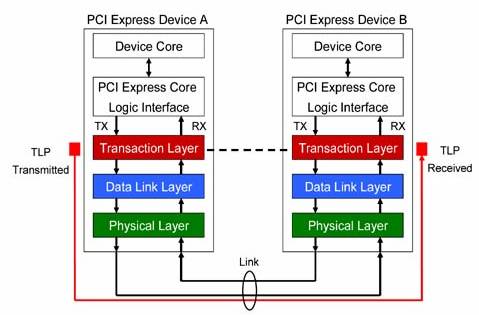
Figure: 1
1.2 Primary Responsibility
The primary responsibility of Transaction Layer is the assembly and disassembly of Transaction Layer Packets. These Transaction Layer Packets (TLPs) are forwarded from one link to another as necessary, subject to the routing mechanisms and rules.
1.3 Transaction Types
The various transaction types supported by the PCI Express compatible devices are:
• Read
• Write
• Base Line (For messages)
• Vendor Specific
1.4 Addressing Formats
As transactions are carried out between PCI Express requesters and completers, four separate address spaces are used: Memory, IO, Configuration, and Message. The basic use of each address space is described in Table 1.
Table: 1 PCI Express Address Space And Transaction Types |
Address Space |
Transaction Types |
Purpose |
Memory |
Read,
Write |
Transfer data to or from a location in the system memory map |
IO |
Read,
Write |
Transfer data to or from a location in the system IO map |
Configuration |
Read,
Write |
Transfer data to or from a location in the configuration space of a PCI-compatible device. |
Message |
Baseline,
Vendor-specific |
General in-band messaging and event reporting (without consuming memory or IO address resources) |
1.5 Possible types of Transactions
There are two types of transactions which are supported by the PCI Express compatible devices. They are:
• Posted type transactions
These are the type of transactions which do not require completion of a transaction.
• Non-Posted type transactions
These are the type of transactions which require completion of a transaction.
To mitigate the penalty of the request-completion latency, messages and some write transactions in PCI Express are posted, meaning the write request (including data) is sent, and the transaction is over from the requester's perspective as soon as the request is sent out of the egress port; responsibility for delivery is now the problem of the next device. In a multi-level topology, this has the advantage of being much faster than waiting for the entire request-completion transit, but as in all posting schemes uncertainty exists concerning when (and if) the transaction completed successfully at the ultimate recipient.
In PCI Express, write posting to memory is considered acceptable in exchange for the higher performance. On the other hand, writes to IO and configuration space may change device behavior, and write posting is not permitted. A completion will always be sent to report status of the IO or configuration write operation.
Table: 2 PCI Express Posted and Non-Posted Transactions |
Request |
How Request Is Handled |
Memory Write |
All Memory Write requests are posted. No completion is expected or sent. |
Memory Read
Memory Read Lock |
All memory read requests are non-posted. A completion with data (CplD or CplDLK) will be returned by the completer with requested data and to report status of the memory read |
IO Write |
All IO Write requests are non-posted. A completion without data (Cpl) will be returned by the completer to report status of the IO write operation. |
IO Read |
All IO read requests are non-posted. A completion with data (CplD) will be returned by the completer with requested data and to report status of the IO read operation. |
Configuration Write
Type 0 and Type 1 |
All Configuration Write requests are non-posted. A completion without data (Cpl) will be returned by the completer to report status of the configuration space write operation. |
Configuration Read
Type 0 and Type 1 |
All configuration read requests are non-posted. A completion with data (CplD) will be returned by the completer with requested data and to report status of the read operation. |
Message
Message With Data |
While the routing method varies, all message transactions are handled in the same manner as memory writes in that they are considered posted requests |
1.6 Transaction Layer Services
The Transaction Layer, in the process of generating and receiving TLPs, exchanges Flow Control information with its complementary Transaction Layer on the other side of the Link. It is also responsible for supporting both software and hardware-initiated power management.
A Transaction Layer's Packet generation and processing services require it to:
• Generate TLPs from device core Requests
• Convert received Request TLPs into Requests for the device core
• If end-to-end data integrity is supported, generate the end-to-end data integrity CRC and update the TLP header accordingly
1.7 Transaction/Data Link Interface
The Transaction to Data Link interface provides:
• Byte or multi-byte data to be sent across the Link
• Local TLP-transfer handshake mechanism
1.8 Three Methods of TLP Routing
All of the TLP variants, targeting any of the four address spaces, are routed using one of the three possible schemes: Address Routing, ID Routing, and Implicit Routing. Table 3 summarizes the PCI Express TLP header type variants and the routing method used for each. Each of these is described in the following sections.
Table: 3 PCI Express TLP Variants and Routing Options |
TLP Type |
Routing Method Used |
Memory Read (MRd), Memory Read Lock (MRdLk), Memory Write (MWr) |
Address Routing |
IO Read (IORd), IO Write (IOWr) |
Address Routing |
Configuration Read Type 0 (CfgRd0), Configuration Read Type 1 (CfgRd1) Configuration Write Type 0 (CfgWr0), Configuration Write Type 1(CfgWr1) |
ID Routing |
Message (Msg), Message With Data (MsgD) |
Address Routing, ID Routing, or Implicit routing |
Completion (Cpl), Completion With Data (CplD) |
ID Routing |
1.9 The Process of Assembly and Disassembly of TLPs
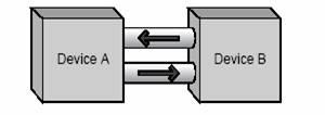
Figure: 2
• Device B's core passes a request for service to the PCI Express hardware interface. How this done is not covered by the PCI Express Specification, and is device-specific. General information contained in the request would include:
• The PCI Express command to be performed
• Start address or ID of target (if address routing or ID routing are used)
• Transaction type (memory read or write, configuration cycle, etc.)
• Data payload size (and the data to send, if any)
• Virtual Channel/Traffic class information
• Attributes of the transfer: No Snoop bit set?, Relaxed Ordering set?, etc.
• The Transaction Layer builds the TLP header, data payload, and digest based on the request from the core. Before sending a TLP to the Data Link Layer, flow control credits and ordering rules must be applied.
• When the TLP is received at the Data Link Layer, a Sequence Number is assigned and a Link CRC is calculated for the TLP (includes Sequence Number). The TLP is then passed on to the Physical Layer.
• At the Physical Layer, byte striping, scrambling, encoding, and serialization are performed. STP and END control (K) characters are appended to the packet. The packet is sent out on the transmit side of the link.
• At the Physical Layer receiver of Device A, de-serialization, framing symbol check, decoding, and byte un-striping are performed. Note that at the Physical Layer, the first level or error checking is performed (on the control codes).
• The Data Link Layer of the receiver calculates CRC and checks it against the received value. It also checks the Sequence Number of the TLP for violations. If there are no errors, it passes the TLP up to the Transaction Layer of the receiver. The information is decoded and passed to the core of Device A.
• The Data Link Layer of the receiver will also notify the transmitter of the success or failure in processing the TLP by sending an Ack or Nak DLLP to the transmitter. In the event of a Nak (No Acknowledge), the transmitter will re-send all TLPs in its Retry Buffer.
1.10 General Packet Format Overview
Transactions consist of Requests and Completions, which are communicated using packets. Figure below shows a high level serialized view of a Transaction Layer Packet (TLP), consisting of a TLP header, a data payload (for some types of packets), and an optional TLP digest.

Figure: 3
PCI Express conceptually transfers information as a serialized stream of bytes as shown in figure above. Note that at the byte level, information is transmitted/received over the interconnect with byte 0 being transmitted/received first.
Detailed layouts of the TLP header and TLP digest are drawn with the lower numbered bytes on the left rather than on the right as has traditionally been depicted in other PCI specifications. The PCI Express header layout is optimized for performance on a serialized interconnect, driven by the requirement that the most time critical information be transferred first. For example, within the PCI Express TLP header, the most significant byte of the address field is transferred first so that it may be used for early address decode.
Payload data within a TLP is depicted with the lowest addressed byte shown to the upper left.

Figure: 4
1.11 Type of Transaction Model used in the project
The transaction type model created by us utilizes Message Type Transaction . Message requests replace many of the interrupt, error, and power management sideband signals used on earlier bus protocols. All message requests use the 4DW header format, and are handled much the same as posted memory write transactions. Messages may be routed using address, ID, or implicit routing. The routing subfield in the packet header indicates the routing method to apply, and which additional header registers are in use (address registers, etc.).
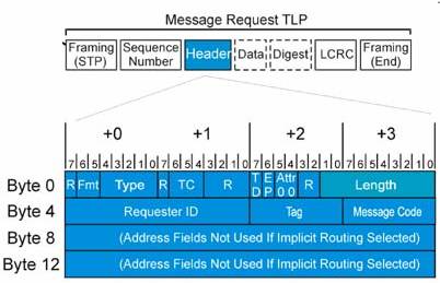
Figure: 5
Depending on the type of a packet, the header for that packet will include some of the following types of fields:
• Format of the packet
• Type of the packet
• Length for any associated data
• Transaction Descriptor, including:
• Transaction ID
• Attributes
• Traffic Class
• Address/routing information
• Byte Enables
• Message encoding
• Completion status
All TLP fields marked Reserved (sometimes abbreviated as R) must be filled with all 0's when a TLP is formed. Values in such fields must be ignored by Receivers.
1.12 Definitions Of Message Request Header Fields
Table 4 describes the location and use of each field in a message request header.
Table: 4 Message Request Header Fields |
Field Name |
Header Byte/Bit |
Function |
Length 9:0 |
Byte 3 Bit 7:0
Byte 2 Bit 1:0 |
Indicates data payload size in DW. For message requests, this field is always 0 (no data) or 1 (one DW of data) |
Attr 1:0 (Attributes) |
Byte 2 Bit 5:4 |
Attribute 1 : Relaxed Ordering Bit
Attribute 0 : No Snoop Bit
Both of these bits are always = 0 in message requests. |
EP |
Byte 2 Bit 6 |
If = 1, indicates the data payload (if present) is poisoned. |
TD |
Byte 2 Bit 7 |
If = 1, indicates the presence of a digest field (1 DW) at the end of the TLP (preceding LCRC and END) |
TC 2:0 (Transfer Class) |
Byte 2 Bit 6:4 |
Indicates transfer class for the packet. TC is = 0 for all message requests. |
Type 4:0 |
Byte 0 Bit 4:0 |
TLP packet type field. Set to:
Bit 4:3:
10b = Msg
Bit 2:0 (Message Routing Subfield)
000b = Routed to Root Complex
001b = Routed by address
010b = Routed by ID
011b = Root Complex Broadcast Msg
100b = Local; terminate at receiver
101b = Gather/route to Root Complex
0thers = reserved |
Fmt 1:0 (Format) |
Byte 0 Bit 6:5 |
Packet Format. Always a 4DW header
01b = message request without data
11b = message request with data |
Message Code 7:0 |
Byte 7 Bit 7:0 |
This field contains the code indicating the type of message being sent.
0000 0000b = Unlock Message
0001 xxxxb = Power Mgmt Message
0010 0xxxb = INTx Message
0011 00xxb = Error Message
0100 xxxxb = Hot Plug Message
0101 0000b = Slot Power Message
0111 111xb = Vendor Type 0 Message
0111 1111b = Vendor Type 1 Message |
Tag 7:0 |
Byte 6 Bit 7:0 |
As all message requests are posted, no tag is assigned to them. These bits should be = 0. |
Requester ID 15:0 |
Byte 5 Bit 7:0
Byte 4 Bit 7:0 |
Identifies the requester sending the message.
Byte 4, 7:0 = Requester Bus #
Byte 5, 7:3 = Requester Device #
Byte 5, 2:0 = Requester Function # |
Address 31:2 |
Byte 11 Bit 7:2
Byte 10 Bit 7:0
Byte 9 Bit 7:0
Byte 8 Bit 7:0 |
If address routing was selected for the message (see Type 4:0 field above), then this field contains the lower part of the 64-bit starting address. Otherwise, this field is not used. |
Address 63:32 |
Byte 15 Bit 7:2
Byte 14 Bit 7:0
Byte 13 Bit 7:0
Byte 12 Bit 7:0 |
If address routing was selected for the message (see Type 4:0 field above), then this field contains the upper 32 bits of the 64 bit starting address. Otherwise, this field is not used.
|
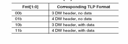
Figure: 5
1.13 Format Bits
Message routing is determined using the r[2:0] sub-field of the Type field and Message Routing r[2:0] values are defined in Table 5.
Permitted values are defined in the following sections for each Message
Table: 5 Message Routing
r[2:0]
|
Description |
000 |
Routed to root complex |
001 |
Routed by address |
010 |
Routed by ID |
011 |
Broadcast from Root complex |
100 |
Local-Tetminate at receiver |
101 |
Gathered and routed to root complex |
110-111 |
Reserved-Terminate at receiver |

Length field encodings
Figure: 6
1.14 TLPs with Data Payloads Rules
• Length is specified as an integral number of DW
• Length [9:0] is reserved for all Messages except those which explicitly refer to a Data Length.
• The value in the Length field applies only to data the TLP Digest is not included in the Length.
1.15 TLPs Digest rules
• For any TLP, a value of 1b in the TD field indicates the presence of the TLP Digest field including an ECRC value at the end of the TLP .
• A TLP where the TD field value does not correspond with the observed size
(accounting for the data payload, if present) is a Malformed TLP.
• This is a reported error associated with the Receiving Port.
• If the device at the ultimate destination of the TLP does not support ECRC checking the device must ignore the TLP Digest
• ?. If the device at the ultimate destination of the TLP supports ECRC checking, the
• device interprets the value in the TLP Digest field as an ECRC value.
1.16 Transaction Descriptor
1.16.1 Overview
The Transaction Descriptor is a mechanism for carrying Transaction information between the Requester and the Completer. Transaction Descriptors are composed of three fields:
• Transaction ID identifies outstanding Transactions
• Attributes field specifies characteristics of the Transaction
• Traffic Class (TC) field associates Transaction with type of required service
Figure: 7
1.16.2 Transaction Descriptor Transaction ID Field
The Transaction ID field consists of two major sub-fields: Requester ID and Tag as shown:
Figure: 8
• For Requests which do not require Completion (Posted Requests), the value in the Tag [7:0] field is undefined and may contain any value.
• For Posted Requests, the value in the Tag [7:0] field must not affect Receiver processing of the Request.
• Requester ID and Tag combined form a global identifier, i.e., Transaction ID for each Transaction within a Hierarchy.
• Transaction ID is included with all Requests and Completions.
1.16.3 Transaction Descriptor Attributes Field
Transactions within the system, such as:
• Ordering
• Hardware coherency management (snoop)
Figure: 9
1.16.4 Relaxed Ordering Attribute
This attribute is not applicable and must be set to 0 for configuration requests, I/O requests, memory requests that are Message Signaled Interrupts, and Message requests.
1.16.5 No Snoop Attribute
This attribute is not applicable and must be set to 0 for configuration requests, I/O requests, memory requests that are Message Signaled Interrupts, and Message requests.
1.16.6 The project involves message passing with Implicit Routing
• PCI Express Adds Implicit Routing for Messages.
• PCI Express adds the third routing method, implicit routing, which is an option when sending messages. In implicit routing, neither address nor ID routing information applies; the packet is routed based on a code in the packet header indicating it is destined for device(s) with known, fixed locations (the Root Complex, the next receiver, etc.).
• While limited in the cases it can support, implicit routing simplifies routing of messages.
• Note that messages may optionally use address or ID routing instead.
1.16.7 Advantages of using implicit routing
The advantage of implicit routing is that it eliminates the need to assign a set of memory mapped addresses for all of the possible message variants and program all of the devices to use them. ( i.e. the need for presetting the devices or the address spaces for which a particular device would respond is eliminated; just the target device has to be identified.)
Our project involves use slot power limit message coding which takes the following form.
Unlock Message |
Message Code 7:0 |
Routing 2:0 |
Set_Slot_Power_Limit |
0101 0000b |
100b |
Figure: 10
1.16.8 Set_Slot_Power_Limit Message Rules
• These messages are required to use the default traffic class, TC0. Receivers must check for violation of this rule (handled as Malformed TLPs).
• This message type carries a data payload of 1 DW. The Length field is set = 1. Only the lower 10 bits of the 32-bit data payload is used for slot power scaling; the upper bits in the data payload must be set = 0.
1.17 ECRC Generation and Checking
The End to End Cyclic Redundancy Check is a method used for checking the integrity of the data sent by the requester device. The ECRC includes all invariant fields of the TLP header and the data payload, if present. All variant fields are set to 1 for calculating the ECRC, include:
• Bit 0 of the Type field is variant this bit changes when the transaction type is altered for a packet. For example, a configuration transaction being forwarded to a remote link (across one or more switches) begins as a type 1 configuration transaction. When the transaction reaches the destination link, it is converted to a type 0 configuration transaction by changing bit 0 of the type field.
• Error/Poisoned (EP) bit this bit can be set as a TLP traverses the fabric in the event that the data field associated with the packet has been corrupted. This is also referred to as error forwarding.
Who Can Check ECRC?
The ECRC check is intended for the device that is the ultimate recipient of the TLP. Link CRC checking verifies that a TLP traverses a given link before being forwarded to the next link, but ECRC is intended to verify that the packet sent has not been altered in its journey between the Requester and Completer.
1.17.1 ECRC Rules
The capability to generate and check ECRC is reported to software, and the ability to do so is enabled by software.
? ?If a device is enabled to generate ECRC, it must calculate and apply ECRC for all TLPs originated by the device Switches must pass TLPs with ECRC unchanged from the Ingress Port to the Egress Port.
? ?If a device reports the capability to check ECRC, it must support Advanced Error Reporting. If a device is enabled to check ECRC, it must do so for all TLPs received by the device including ECRC.
• ?Note that it is still possible for the device to receive TLPs without ECRC, and these are processed normally this is not an error. A 32-bit ECRC is calculated for the entire TLP (header and data payload) using the following algorithm and appended to the end of the TLP (see Figure):
• The ECRC value is calculated using the following algorithm (see Figure below).
The polynomial used has coefficients expressed as 04C1 1DB7h
The seed value (initial value for ECRC storage registers) is FFFF FFFFh
All invariant fields of the TLP header and the entire data payload (if present) are included in the ECRC calculation, all bits in variant fields must be set to 1 for ECRC calculations.
• ?Bit 0 of the Type field is variant16
• ?The EP field is variant
• ?all other fields are invariant. ECRC calculation starts with bit 0 of byte 0 and proceeds from bit 0 to bit 7 of each byte of TLP.
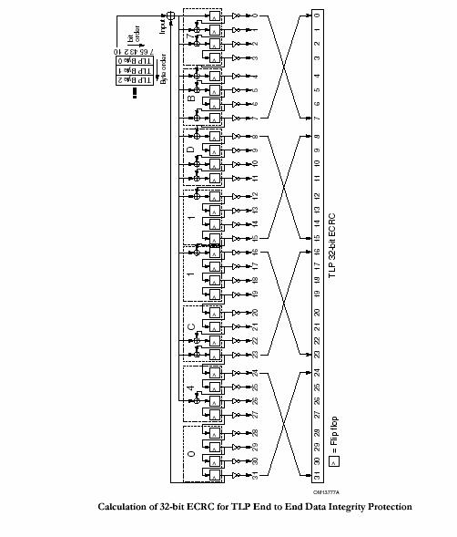
Figure: 11
1.17.2 The Mapping of ECRC:
Table: 6 Mapping of Bits into ECRC Field
1.18 Handling of Received TLPs
In general the checks to be performed at receiver are as follows:
As TLPs arrive at an ingress port, they are first checked for errors at both the physical and data link layers of the receiver. Assuming there are no errors, TLP routing is performed; basic steps include:
• The TLP header Type and Format fields in the first DWord are examined to determine the size and format of the remainder of the packet.
• Depending on the routing method associated with the packet, the device will determine if it is the intended recipient; if so, it will accept (consume) the TLP. If it is not the recipient, and it is a multi-port device, it will forward the TLP to the appropriate egress port--subject to the rules for ordering and flow control for that egress port.
If it is neither the intended recipient nor a device in the path to it, it will generally reject the packet as an Unsupported Request (UR).
The following section describes how all Received TLPs are handled when they are delivered to the Receive Transaction Layer from the Receive Data Link Layer, after the Data Link Layer has validated the integrity of the received TLP.
The rules are diagramed in the flowchart shown in Figure.
• Values in Reserved fields must be ignored by the Receiver.
• All Received TLPs which fail the required (and implemented optional) checks of TLP formation rules described in this chapter, or which use undefined Type field values, are Malformed TLPs (MP) and must be discarded without updating Receiver Flow Control information
• This is a reported error associated with the Receiving Port ,Otherwise, update Receiver Flow Control tracking information
• If the value in the Type field indicates the TLP is a Request, handle according to Request Handling Rules, otherwise, the TLP is a Completion handle according to Completion Handling Rules
• If the value in the Type field indicates the TLP is a Msg or MsgD Request, route the Request according to the routing mechanism indicated in the r[2:0] sub-field of the Type field.
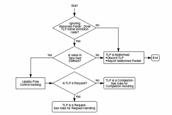
Figure: 12 Flow Chart for Handling of Received TLPs
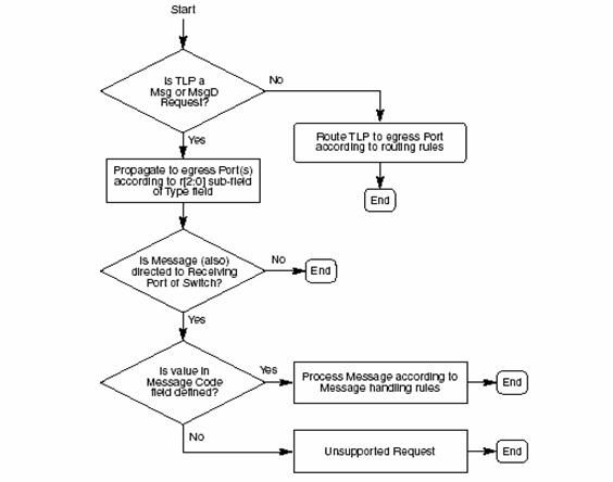
Figure: 13 Flow Chart for Switch Handling of TLPs
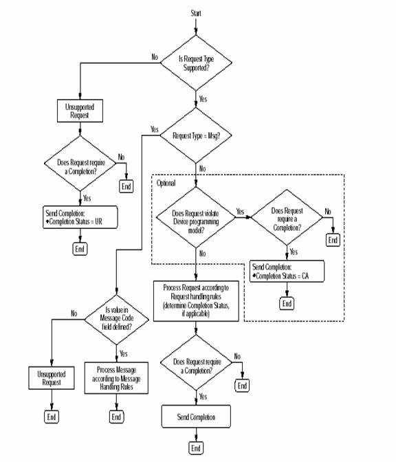
Figure: 14 The Flow Chart for handling of Received Request