Homemade CNC Router
This is an overview of my experiences and steps taken to build a hobby CNC router, with a minimum of investment in time and funds. The intended end use is for cutting parts in balsa sheets or thin plywood for model building.

What you need to get going:
- Router or high speed rotary tool
- XYZ table with stepper motors
- PC Interface to drive stepper motors
- Software to run the CAM files
- And likely software to generate CAD/CAM files, if you don’t have any CNC files to run.
Beside these items, some practical knowledge and understanding of mechanical and electronic design and construction techniques is an asset, as you’re not putting together a BBQ bought at a hardware store!
The Router
For a router, I found at a pawnshop a used variable speed rotary hand tool. Dremel is a fairly well known brand, but mine is a model made by Mastercraft for the Canadian Tire retail store.
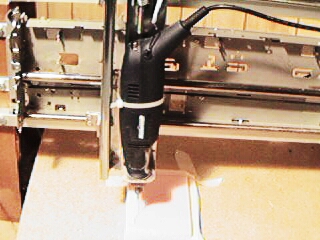
The problem with most hand held tools is that they are not designed or built to provide great accuracy in the ‘tightness’ of the spindle. I could feel some sideways free play in mine, so I decided to take it apart to identify the source of the movement. This is usually the Achilles’ heel in homemade routers with respect to precision of cuts.
What I found were two basic flaws. The spindle shaft is supported by two good size bearings, but they are somewhat loosely fitted in the plastic casing. Since the tool is going to be clamped to the Z-axis of the table, the fit of the bearing to the case needs to be as solid as possible. This can be achieved a couple of ways. Some tape between the bearings and the case can be added to make the fit even tighter. Epoxy glue could also be used to make the fit a little more secure.
The other flaw is that the bearings are fairly close to each other, less than an inch apart. Luckily on the model I have, the end bearing comes off easy. I simply relocated it at the end of the tool, between the casing and the screw end cap. This modification provided two things. It almost doubled the distance between the bearings, and therefore cut theoretically the free play in half. Securing the bearing against the screw end cap provided a very tight fit of the bearing to the casing. Now, I can’t even feel any free play on the spindle.
For cutting soft material like foam, balsa or plywood, carbide end mills are best suited for the job. You can find 1/8” shank tools at specialty tool shops, which will last longer and cut better than Dremel router bits.
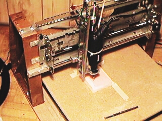
XYZ table with stepper motors
The next consideration is how big are the parts you intend to machine. In my case, I wasn’t looking to cut very big parts, and a 15” x 15” working area would be sufficient for most of my needs. The other consideration is that the bigger the working area, the more mass and therefore power needed to drive the table. A common method used by several hobbyists is to use threaded rods attached to the stepper motors, and build a sliding system to support to base to be driven. Since my goal was to build something as simple as possible with minimal construction, I found two old printers at an electronic recycler that were driven by a stepper motor with a cogged belt drive system, which had a 15” wide travel path. All I had to do was to take the printers apart to get the drive system out. Drawer slides were also use to support each axis, as the printer drives were fairly small. I found that using two drawer slides at right angle to each other provided a reasonable level of accuracy in supporting each axis.The table itself is made of particle board, while the vertical supports are molded bench supports found at the hardware store.
PC Interface
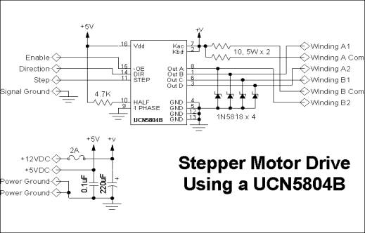
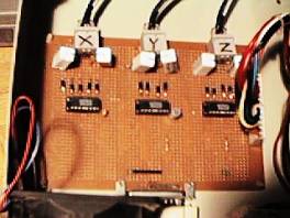
An interface is needed to get commands sent from the PC parallel port to the stepper motors. Allegro Micro Systems make a control chip that is good up to 35V and 1.25A. They may be difficult to find, but are available on the web by mail order from various places. You may be able to get samples directly from the chip manufacturer . The following circuitry is replicated three times, to drive the three motors used for each axis. Power resistor values may vary, depending on the motors used. The documentation on this I/F card (scroll down to bb2001-3z.zip) was also useful in the layout of my card.
The interface is housed in an old PC box, to use its power supply to drive the interface and the stepper motors. I used RJ45 connectors and cables to connect the interface to the motors.
Software
Basically, you need some software to run G code commands to the hardware. TurboCNC (http://www.dakeng.com/turbocnc.html) is a nice DOS based software that can be used to set up your hardware to run CNC files. It allows you to send text commands from the PC to move up to eight axis. It’s also used to calibrate your stepper motor speed and travel per step parameters. DAK Engineering also provides a ZBREAK utility that allows you to operate a 2D system, while you manually index the third axis for the tool. This utility allows you to run a 2.5 or 3D file with only an X-Y table, that could be installed under a drill press.
G code is just simple ascii text, and could be generated manually by typing coordinates. However, the most common method used to generate G code is to take a computer image file and convert it. ACE Converter (http://www.yeagerautomation.com/ace.htm) from Yeager Automation converts DFX files into G code directly for routing. It’s part of their CNCpro download file.
Deskam offers freeware to create text to G code files, which can be used to route signs. The software is called deskengrave
For 3D machining, ACME Profiler (http://www2.fwi.com/~kimble/scispec/scispec.htm)
from Science Specialists does a nice job at converting several image formats
into G code, by using grey scale to vary the Z axis positions. The software
also lets you visualize the 3D machining before you commit to carving anything. For running a virtual CNC run before committing to cutting material, AutoEditCNC
does a pretty good job at simulating the tool path from the CNC file. AutoCAD or TurboCAD are two of the most
popular CAD software tools used to generate and edit DFX files. Depending on
the CAM software used, you may need to modify the design to include the cutting
tool offset (half of its diameter), if it can’t be programmed as a parameter
directly in the CAM application. This project was completed within two weeks
of getting all the parts. I’m running TurboCNC on a dedicated Pentium 75 laptop
in DOS mode, and it’s quite sufficient for the task. Other CAD activities, as
well as CAM file editing are done on another more ‘modern’ PC in Windows. Some calibration was needed to define the
proper parameters for the drive, with respect to motor rotation and actual
movement. This is done through the TurboCNC settings, while jogging the table
and using a precise ruler. In the end, I did achieve what I set out to
do, which was to get a working homemade unit made with a minimum of cost and
labour. I did not keep track of all the related costs, but I estimate with all
the scrounging I did was under CDN$200. Conclusion