Propellor Jaqua Systems http://www.geocities.com/vjaqua/props.htm
THE COMMON MAN'S APPROACH TO PROPELLER THEORY AND DESIGN
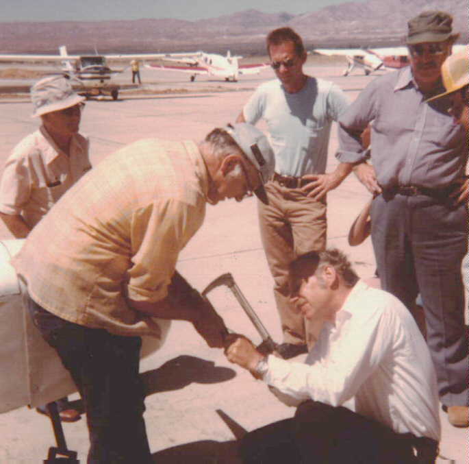
After a near lifetime in aerospace propulsion (mostly Jets and Rockets), I was involved in the design and construction of a small, single place light weight monoplane powered by a direct drive two stroke engine. This was way off scale from any data base that was readily available for propeller design. We carved several props, with various degrees of poor results, bogging the two stroke down out of it's useful power range. It flew with one of these props, actually after we made a field modification, cutting an inch off each tip. We later got a plausible power curve for the engine and determined that it had flown on roughly 12 of the advertised 25 BHP. The plane flew out of ground effect at the roughly 6000 ft density altitude, but the lack of rate of climb limited the flights to straight ahead on Mojave's rather lengthy run way. This experience has led to a long term vendetta to understand, and provide guidelines for the design of fixed pitch propellers.
Here is the propeller surgery under way using a precision hacksaw in the hands of a much younger V. Jaqua
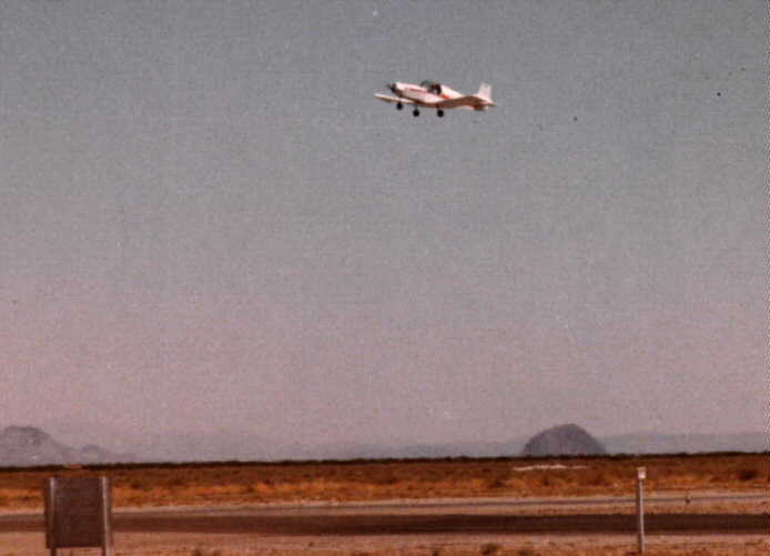
This view shows that the plane flew well enough to get out of ground effect. However, with a very marginal rate of climb, each of the flights were straight ahead over the long runway at Mojave.
UNDERSTANDING PROPELLERS - WITHOUT THE BRAIN BREAK ING MATH
To understand how and why propellers work, we will go back to basics of heavier than air flight, and forget for a moment that we are interested in rapidly spinning, carefully crafted sticks. Man's first association with heavier than air flight was watching the birds fly. Birds, of course, do not have propellers, since fully rotating member did not seem to make it through the evolution cycle. However, birds fly using the dame laws of physics as airplanes, and for that matter, jets, helicopters, and even moon rockets. All use the primary force producer known as momentum. This is basically very simple, you grab something and throw it away as hard as you can. The old saw about equal and opposite reaction then comes into play, and the force it took you to throw it, is what pushes you forward, or up, or what ever direction you were trying to go. The bird does it by flapping his wings, grabbing air and throwing in back and down, The propeller and jet does it by "sucking" in a great gulp of air and spewing it out the back. The poor rocket, particularly when it gets in space, has to do it by throwing back material (fuel and oxidizer) that it had carried that far. The force from momentum is mathematically described as MV (mass times the velocity supplied to that mass). In the English engineering units that we generally use, inertial mass is the physical weight in pounds, divided by the gravitational constant (32.17 ft per second, per second), and the velocity is in ft per second. When you do the mathematical operation and cross out the balanced units, the answer comes out in pounds force (our usual description of thrust). Once you have determined that there is a force, and a velocity, the next question is what is the power, or energy expended in making that force. With a mass in motion, it represents a computable amount of energy, what is generally called kinetic energy. This is also represented by a rather simple equation- mass times velocity squared, divided by 2, and the English units value being pounds feet ( this process can be envisioned in that energy could theoretically be extracted as the force remains constant while the velocity is returned to zero (averaged value being half that velocity). This little physics class may seem to lack relevance, but these relationships will become valuable when we explore using engine horsepower (energy) to make the thrust which will accelerate our airplane, permit it to climb, and propel it at useful speeds.
Getting closer to the propellers that we promised to help you understand, The mass that we are going to accelerate for a classic airplane propeller, is roughly a sort of cylinder of air the size of which is related to the diameter of the prop. At the static condition,where you are running up rpm with the brakes locked, the propeller "disk" creates a low pressure area that "sucks" in air which is blown back. Of course "sucks" is in error, since air is blown into the low pressure area by the static pressure in the surrounding atmosphere (thus this inlet velocity is limited to the velocity represented by this local atmospheric pressure - i.e. 14.7 psia on a standard sea level day - regardless of how much power you have available to apply to this propeller (or jet engine inlet)..The size of that cylinder of air controls the amount of weight flow through the prop disk (That all important M in our thrust and power calculations that we discussed above). Now using that MV formula, we can get 100 pounds force of thrust by either accelerating 1 unit of mass by 100 feet per second, or by accelerating 100 units of mass by 1 foot per second, (or any other combination for which the answer is 100). However, remember the expression for power - M times velocity squared, divided by two. This puts a big difference on how much power we need to make the force. The 100 feet per second case computes to 5,000 ft pounds of energy, where the 1 foot per second case is only 50 foot pounds. This is for the static thrust case, and explains why helicopters and STOL type airplanes use those big, rather slow turning propellers to get off the ground. As the airplane flies faster, the need for those large diameters becomes less important, because now your disk is "running into" lots of pounds per second just because of your forward velocity.
Now, we can put actual numbers on the actual maximum thrust and efficiency as a function of propeller disk (air cylinder) diameter, power, and forward speed. The relationship between propeller diameter, and power, is generally referred to as disk loading, and useful English units are horsepower per square foot of disk area. For example, the Piper Cub with 65 HP and a 6 foot diameter prop is about has a disc loading about 2.3 HP per square foot, an RV with 200 HP and a 66 inch prop is about 8.4 HP per square foot, and a Reno racer with 3000 HP and a 12 foot prop would be running about 26.5 HP per square foot at full power. At the extreme end of this parameter, a helicopter blade might be as low as 0.25 HP per square foot, and a straight turbojet may be over 1000 HP per square foot. But I think we will leave those alone for the time being. These values also change somewhat as you decrease the engine power by static loading, reduced throttle settings, and density altitude, but it puts us in the rough ball park.
The enclosed curves show the impact of these parameters on maximum available thrust and "propeller efficiency" (you will understand why I put these words in quotes as you read on). These curves represent the perfect conversion of input horsepower to stream horsepower within the disk area column of sea level standard air. The first curve shows the absolute maximum thrust for each disk loading over a range of aircraft speeds.
Now if you had access to the proverbial "sky hook" with a perfect infinite ratio transmission, and the weightless, flexible non extensible cable, so fondly used in theoretical physics, the thrust at zero speed would be infinite. As speed increased the result would be the classic 550 foot pounds per second, divided by the speed in feet per secnd The resultant force would be the value described by the upper dotted line, described as "one HP perfectly geared. Since sky hooks are in notoriously short supply, we are using our friend momentum to make force, and the mass flow available is a function of the disk area. As mentioned previously, as we go faster we get more mass just because our "disk" is running into it. Study of this curve suggests as we go faster, the need for large areas becomes less of a factor, and this is why jets with their incredible amounts of power, but rather small holes up front, do pretty well at high speeds (but are fuel hungry dogs at slow speeds).
Now, "propeller efficiency" as usually described by our aerodynamicist friends is the percentage of this perfect geared force is delivered by our prop. Remember, that we described the propellers in these curves as "perfect", delivering all the power supplied to the air stream with no loss. Even the perfect prop that we described, is rated as zero percent efficiency when the airplane is stationary (any value divided by infinity is zero).I do not know about you, but that strikes me as unfair, saying that this impossibly good propeller has zero propeller efficiency. This is why I would prefer to call the classic efficiency "propulsion efficiency", and in my programs I often refer to the efficiency of the prop as a pump as "jet efficiency". The next curve shows our same data in terms of maximum propulsion efficiency available under the different operating conditions with our perfect propellers.
My contention is that the propeller efficiency should only be judged against how good a job the propeller did in converting mechanical power into energy into the air stream. This is where all the losses from the airfoil drag, tip vortices losses, etc. come into play. The overall propulsion efficiency thus becomes the product of the prop pumping efficiency times the maximum attainable efficiency that can be obtained at that operating point.
Actually these curves are not limited to propellers. You may have noticed that there has been no mention of RPM, pitch, airfoils etc. These curves could be applied to any method of moving a fluid. It could be a turbofan, a ramjet, bird's wings, magnetohydrodynamics, or even the hair like cilia use by microbes to move around in fluids. The principles and physics of the problems are the same. But, since the purpose of this exercise is propellers, I guess we will have to talk about those things.
The propeller is a pump, that is what it does, and remarkably well in most cases. The primary mechanism in this case is a rotating wing section providing lift as it rotates around it's pivot point. The angle of this wing section from root to tip is set to provide the desired lift coefficient at the design point forward speed of the aircraft. A fairly widely used airfoil section is the famous Clark Y, which has a flat bottom. With this type of foil, the general approach is to measure the pitch angle from this flat bottom. This is not the zero lift line, the actual best lift to drag ratio for these foils is roughly when stream flow is parallel to this surface, and thus, this is a pretty good design point. One of the very important measurements for a propeller is pitch - generally expressed in inches of apparent advance per each rotation of the prop. Generally one would expect that the "unwrapped" pitch at each station along the blade would be the same, and this is termed "true helical" pitch. In the real world the center section of the prop is backed off for structural reasons, and the fact that this part is frequently blocked by the aircraft, or even covered by a spinner. Propeller designers frequently vary from the true helical pitch for many reasons, some real, and some imagined. Our British cousins frequently refer to the prop as an "airscrew", and equivalent devices on boats are frequently called "screws". The action on a boat, and in flight, are much more like screws in a more solid media, than one might think. At the selected design point, the pitch of your propeller should match the RPM, and inches of expected travel per turn fairly closely.
The wing on an airplane generates lift by throwing air at the ground. This action shows up on the wing surface as pressure area distribution, but this is not classic Bernoulli, as some texts and theorists often state. Back to our momentum equation the lift is the result of a mass of air being accelerated downward, and is directly the MV effect Generally the amount of air mass is quite large and the downward velocity is referred to as "downwash". In our propeller this "downwash" is back wash, and is the V in our MV. At static conditions on the ground, all the velocity through the prop disc is the accelerated velocity. The whirling wing makes a reduced pressure zone in front of the prop, and atmospheric pressure pushes the air into the disk. Now it is "sucking" air from a greater area than the spinning diameter, but the velocity through this area is the controlling mechanism. Now some of the popular propeller theories say that half the delta V (accelerated velocity) is in front of the disk and the other half of the speed increase is behind it. Well, this may make their math work better, but I remember something called Kirchoff's law from electrical networks, and something often called continuity, both of which in the most simple form says what comes into a point has to equal what comes out. Now I do not think that propellers create air, so the weight flow into and out of the disk better be the same. Now you can change the velocity in a cylindrical gas flow by increasing or decreasing the density with static pressure. However, with the pumping and compressing energy being supplied by the prop, I would expect the pressure to be higher behind the prop, and quite likely the velocity here to be lower than in front. This is certainly the case with axial flow compressors, which are really just a bunch of propellers. Now we have all seen the drawings that show the flow necking down venturi fashion behind the propeller, and that is undoubtedly an increase in velocity, turning some of the pressure rise into acceleration, but all the forces were transferred back at the prop blades
PROP SIZING
The general description that people use for ordering a prop is diameter and pitch. This does not tell the whole story, for just as in sizing a wing, where span alone is not enough, the chord is also a factor, the width, and the distribution of this blade width is also even more important for a propeller.
DIAMETER - A rule of thumb suggests that one should use the largest diameter as limited by landing gear clearance and tip speed. For wood props, the generally recommended maximum tip speed is about 800 feet per second (about the same speed as the slug from a 45 automatic. Metal, and high strength composite propellers use thinner tip airfoils, and speeds up to 1000 feet per second are considered usable. While both these velocities are below the standard speed of sound (about 1100 feet per second), transonic effects are starting in those speed ranges, and aerodynamic losses, and high noise levels become limiting factors. In Europe where light plane noise levels are being controlled, even lower tip velocities are recommended.
PITCH - Pitch defines the angle of the airfoil at the various radius sections of the propeller. The most common measure of pitch is based on the angle of the flat bottom of the blade airfoil Frequently the airfoil is a flat bottom section similar to the famous Clark "Y", or many of the similar RAF sections. Some propeller designers chose other airfoils, and reference the chord line for describing pitch. Pitch is quoted in inches, and represents the advance from following this angled line for one complete turn of the propeller. The geometric answer is computed by multiplying the radius of the selected section by two times Pi, (the circumference of that path)and that answer by the tangent of the angle. Conversely, if you are designing a prop, and want to Know the required angle for any section, you reverse this procedure. You multiply the radius of the desired section by two Pi to get the circumference of travel.The angle is the number of degrees represented by the tangent value of the pitch divided by this circumference.
As related earlier, the pitch value is related to engine rpm and anticipated airplane speed. Now this is where people start lying to themselves, resulting inpoorly selected propellers and disappointing performance. Just selecting a large pitch will not make your plane go faster - this is very much a drag and horsepower issue. Proper blade width, and width distribution are related to the engine power available. The most important selection criteria for a fixed pitch propeller is that it has to let the engine make horsepower. During run up, and initial acceleration for take off, even the best fixed prop will bog the engine down to an rpm where you can only get about 75 percent of rated power (usually about 2000 to 2300 rpm for a typical certified engine). If the prop is too big (in any or combination of dimensions) you will get even less rpm and horsepower, to the detriment of take off performance. At the other endof the design range, if you have to close the throttle to keep the rpm down in high speed level flight, you are also not developing the power that you are entitled to. Again losing performance from improper sizing. If you are lucky enough to have contact with other people with the same plane and engine, quiz them on prop makers, size, and results. One test is worth a thousand expert opinions, and at least 100 high powered computer programs.
SLIP - Slip is a commonly used misnomer in describing propeller installed performance. This is usually described as the difference between the theoretical advance of the propeller (As if it were acting like a screw in a solid material), to the actual advance of the aircraft speed. For example, with engine rpm at 2000, 53 inches of pitch would suggest 100 mile per hour. Now, if your true airspeed was 90 miles per hour, these people would say you have 10 percent "slip". This is not slip at all, it just means that the drag of your plane is requiring the prop airfoils to operate at a greater angle of attack (higher lift coefficient) than the zero line that was used for describing pitch. Since the flat bottom foils often used for props can still generate lift at at least a couple of degrees negative, you can have a situation where a low drag airplane might have a negative "slip". This approach is also used by some to mistakenly describe the zero "slip" case as 100 percent propeller efficiency. In truth, the relationship between speed and pitch/RPM has little or no bearing on either propeller efficiency or propulsion efficiency.
At the design point for a fixed pitch propeller, the design lift coefficient may be balanced against blade width, increasing pitch (angle of attack) for the same lift with a narrower blade. If the lift to drag ratio was the same over this range of angle changes, there would be no impact on design point performance. However, just as making the wing smaller on an airplane, the induced drag will usually be increased if the lift coefficient is too high, and off design performance will also be degraded. Experience suggests that a lift coefficient at design point should be near 0.4 (which is close to zero attack angle for many flat bottom prop foils).
PROP DESIGN PROGRAM
The propeller vendetta mentioned earlier, started back in the home computer days of the Apple II and the Radio Shack. Actually two computer programs grew out of this effort. The simplest one is called PROPSIZ, and does just that. It sizes a propeller for the selected design point based on engine power, rpm, and anticipated level flight, full throttle, top speed. The other program is more complex, and computes predicted installed performance of the given prop and engine over an input range of operating points.These progams were written in BASIC, and require operation in good old fashioned DOS. They can be run with BASICA, GWBASIC, or QBASIC. A floppy disk with tehese progams can be obtained from me with only materials, postage, and handling.
The approach taken for both of these programs was the combination of the momentum disk theory, and a method referred to as the strip element theory. Since we are dealing with a rotating wing, with well documented airfoils, one can calculate the lift and drag of each little band (strip) of that wing. All that is needed is the entrance velocity, and the angle of attack. With this information, we use the airfoil data from all the years of experience, and apply the values for lift and drag from these curve and tables. Then we "trig" out the resulting vectors that represent the tangential force resisting rotation (power required) and the vector of force in the direction of flight (thrust). Then sum all the results in these strips, and we have the whole propeller. Duck soup! , except for one nagging question - THE ANGLE OF ATTACK!! To know this angle of attack, we have to know the velocity of the air through the propeller "disk". Well if we knew that velocity, we would already know the thrust and would have the answer. Easy, all we need to find the answer, is to have the answer to start with. Fortunately, all is not lost, with the use of the home computer, we can run a large number of trial and error calculations, and converge on the answer. If we start with a reasonable assumption of velocity through the disk, and calculate both the momentum answer, and the strip element answer, they most likely will not agree. Then we change the assumed velocity in small increments in the appropriate direction until they do agree. In view of the limited computer power at that time, rather large "strips" and somewhat coarse iterations were selected. For the calculations the prop is broken down to the 0.3 radius zone (which includes from 0.2 radius to 0.4 radius) the 0.5, 0.7, and finally the 0.9 radius (from 0.8 to 1.0). With the increased computer power and speed available to us at this time, a finer spacing of strip elements could be accommodated, but results would not change very much. The innermost zone from 0.2 inward, is ignored for several reasons. This represents only 4 percent of the area, and is mostly blocked by the nose of the airplane and any spinner which might be used. Over the rest of the disk, the program strives for a uniform input of horsepower and thrust per unit area, adjusting the blade width distribution to this end.This uniform distribution provides the potential highest performance, although some adjustments to real world conditions will suggest deviation from this goal. For example, the "rotating wing" just like any other wing suffers from tip vortices losses, and a slight unloading near the tip may very well be a useful trade. In the other direction, the flow from the inner portion of the disk is increasing local velocity along the fuselage surface, for added drag which is reducing the installed thrust. In this case, unloading some of the inner portions, and moving some of that energy outward is likely to be an overall benefit in many installations (most of this discussion is based on classic front propeller "tractor" installations, the special circumstances of pusher installations will be addressed later).
PITCH
For the airfoil, and desired design point lift coefficient, the programs use the flat bottom of a Clark Y class airfoil as the pitch description, and sets the design point angle of attack parallel to this surface. This sets a design point Cl (lift coefficient)of about 0.4. The table of lift and drag coefficients in the program are set to correspond to values for a low Reynolds number operating point, with about a 6:1 aspect ratio. With those input values the best lift drag ratio is very near this point (of zero angle of attack using that reference) at roughly 20 to one. The logic of the program can be readily changed to reflect other airfoils, and other reference points such as chord line, or zero lift line, which some aerodynamicists seem to favor.