[ Español ]
Most desktop PCs use fans to cool some internal parts and commonly they are always run at full speed regardless of the cooling needs, turning the PC into a noisy machine. Many times it is not necessary to blow so much air because the parts are not so hot and it would be possible to lower the fan speed to reduce noise without any adverse effect. It is a known hack to add a potentiometer or connect the fan to 7V to lower its noise but these solutions are not recommended since the cooling needs can change radically over time and the user is not aware of that.
In this document we present a simple but effective solution to this problem. The required parts and connections cost the same as the installation of a potentiometer but it is safer and better. With a transistor, an NTC resistor and a small potentiometer it is possible to build a circuit that automatically adjusts fan speed depending on a sensed temperature. Its cost is under one Euro and it reduces fan noise and increases its useful life.
We present two possible schematics using different types of transistors, so it will be easier to find the proper parts. The left one uses a PNP transistor type BC327 or BC328 and the right one an NPN transistor type BC337 or BC338. Both have the same effectiveness and use the same NTC resistor and potentiometer. You must build only one circuit per fan.
The transistor must be the indicated type because it has the proper gain and current capability to achieve a proper adjustment range. Any other type of transistor may not work correctly.
For a proper operation use an NTC resistor with a resistance between 4k and 22k at ambient temperature. Depending on its value the potentiometer value must be:
| NTC value | Potentiometer |
|---|---|
| 4k7 to 8k2 | 470 |
| 10k to 15k | 680 |
| 18k to 22k | 1k |
The potentiometer sets the circuit sensitibity to temperature, increasing its value will increase the sensitivity so the fan will run faster with less heat. It has to be adjusted so the cooled element works at a reasonable temperature when it is dissipating maximum heat.
When correctly setup, at ambient temperature the fan will stop completely. As the temperature sensed increases the fan voltage will increase slowly until it starts to rotate, at that point if the temperature still increases it will accelerate or if it cools easily it will stop again.
It is very important to perform a thorough test to ensure the cooled part will not overheat under any circumstance. If it does adjust the preset to increase sensitivity. Also it is important to hold the NTC to the heat sink safely so it cannot fall off and is subjected to good thermal contact. Mount the NTC in a place where air blown by the fan will not reach it.
It is very important to ensure a good thermal contact exists between NTC and heat sink the fan is cooling. If the heat sink is electrically isolated a good way is to contact one leg directly to the heat sink, only one leg, not both, near the NTC body. Be careful however because some heat sinks may be connected somewhere, in this case electrical isolation must be provided.
It is recommended to solder all connections. If no soldering iron is available the connections can be made twisting wires and components legs together but this may not be reliable. Be very careful not to cause shorts since they can cause irreversible damage to the computer.
The transistor will get warm while in operation so do not solder NTC leg directly to transistor leg, instead use a wire and route it through the fan air flow. If not done this way the transistor will heat the NTC and accelerate the fan without any reason.
If you cannot find the proper NTC values you can use other values connected in series or parallel to get the required values. In series their values add:
and in parallel this formula applies:
This formula works for any number of resistors, not just three. For example two 47k NTC resistors form the equivalent of one 22k NTC resistor. Two 2k resistors in series form one 4k resistor. This way it is possible to use other NTC values connected in series or parallel to build this circuit.
When mounting the NTC resistor to the heat sink select a place the fan air will not reach the NTC. The air would cool it quickly incorrectly lowering the fan speed. Never under any circumstance short the NTC legs together while power is applied to the circuit, there is nothing to limit the current through the transistor base and it will blow instantly.
NTC resistors lower their resistance value when their temperature increases. In this circuit the NTC resistor is part of a voltage divider together with the potentiometer that polarizes the transistor base. When properly calibrated at ambient temperature the voltage at the transistor base-emitter junction is 0.5V, slightly below its conduction threshold so it does not conduct any current and the fan is stopped. When the NTC warms its value lowers thus increases the base-emitter voltage. At 0.6V the trasistor junction starts to draw current and it works as a current amplifier, letting some current to the fan. The higher the temperature the more current it will draw and more current will be allowed to the fan, adjusting its speed depending on the NTC temperature.
The selected transistor has a gain between 100 and 300 that is adequate for the typical PC fan. Selected NTC values provide between two and three times the needed current to fully polarize the transistor and the potentiometer takes part of this current so the operation range can be adjusted. The use of a transistor to amplify current allows us to use smaller and higher NTC values that are cheaper and easier to find.
With NTC values above 22k the temperature response is too flat and does not accelerate sufficiently at higher temperatures. On the other hand with values smaller than 4k there is a risk of circuit self destruction due to self-heating.
The process starts soldering the components according to the corresponding schematic. Fan wire should be cut at the proper length keeping in mind the place where the NTC will be held. The following photo shows the circuit built for a BC327 PNP transistor:
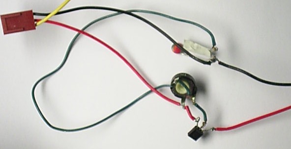
Note the length of green wire to keep the transistor from heating the NTC. This wire will be placed between heat sink fins.
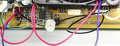
The following image is another prototype using a BC337 NPN transistor. The yellow wire is placed between heat sink fins and the green wire connects to the same NTC pin. The transistor is placed in a heat sink fin with its type number facing upwards.
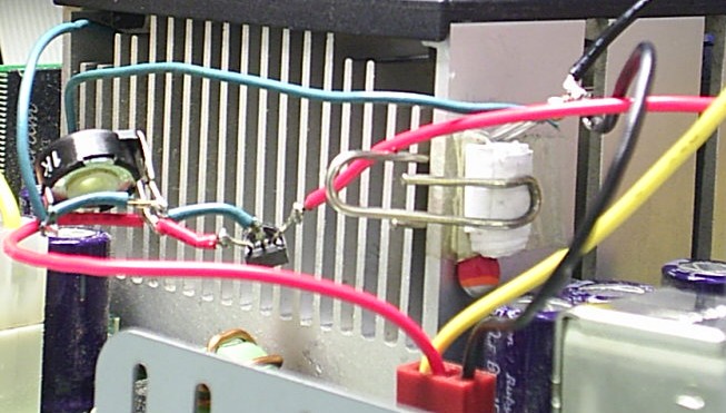
Below you can see two ways to stick the NTC to the CPU heat sink. The first one uses a bent paper clip and a small strip of paper in front of the NTC terminals. Both terminals are electrically isolated and the NTC body is in contact with heat sink metal. The second one uses a screw and nut to hold the NTC by one leg. Remember the NTC must not be hit by the fan air and double-check the heat sink is not electrically connected somewhere before you do like the second picture.
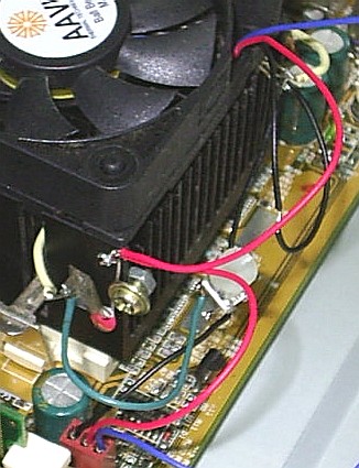
This photo shows this circuit built in a video card fan. To hold the NTC a wire is soldered to one leg and passed through a heat sink fin.
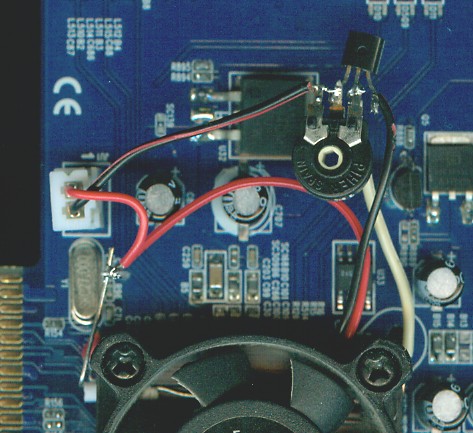
The NTC is at the fan left side and its soldered wire shows up at the right side (yellow wire). A paper strip is inserted in the heat sink fin to keep the NTC leg in touch with heat sink metal and stop air flow from reaching it.
Warning! Inside a power supply there are dangerous voltages even when unplugged that could cause death. You do this section at your risk.
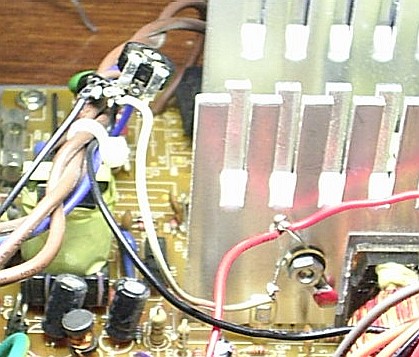
To start check the heat sink that gets hottest, usually this is the biggest heat sink at the middle where the rectifiers are attached. This is where the NTC must be installed.
This photo shows how we mounted the NTC. First we double checked the heat sink is not electrically connected anywhere (if connected somewhere it is not possible to do this, then both legs must be electrically isolated). A female nut has been added in an existing screw and the left NTC leg electrically isolated with electrical tape. This place was selected because it is well protected from fan air flow.
It is important to double check the circuit cannot accidentally move or short anywhere. A short could destroy the power supply and PC beyond repair.
Finally we verify it works properly and nothing overheats in the supply. When run without its cover the fan accelerates considerably because the air is not forced through the inside, do not run for a long time this way. With the cover installed the fan runs slower that indicates it is cooling properly.
Generally the power supply fan will never stop completely because the rectifiers get quite hot even when the PC is idling, this is desired so there will be some air flow inside the PC box.
After installing this regulator in a PC I have reduced its noise notoriously. Now the hard disk has become the predominant noise and I can install my multimedia PC in our living room without noise complaints.
Project completed on July 2007 by Jeroni Paul.
Copyright © 2007 Jeroni Paul.