[ Español ]
This is my first digital clock using nixies to display the time. Nixies were invented in the fifties but were soon replaced by LEDs, fluorescent displays or LCDs and nowadays are valuable antiques. A nixie consists of a sealed glass tube filled with gas, typically neon, a grid and ten electrodes each shaped like a number. When enough voltage is applied between the grid and one electrode, gas around that electrode ionizes and glows displaying the corresponding number.
This project is possible thanks to Estebitan, Miguel Gimenez and Ronald Dekker. Estebitan sent me an old board with three nixies and some 74xx TTL ICs I use in this clock, Miguel Gimenez gave me another nixie and Ronald Dekker provided a larger neon bulb for the tens of hours. Thank you very much!
Whenever possible I used original components and circuit design common in the seventies so this clock keeps that vintage electronics style.
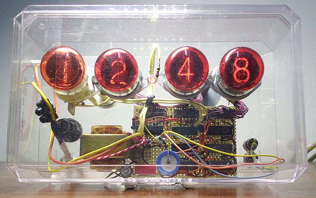
This is my clock finished. Click on the picture to enlarge:
I have mounted it in a transparent box of chocolates where I have drilled holes to screw the board, nixies, push buttons and to let in air flow for cooling. The nixies are inside the box secured with spacers.
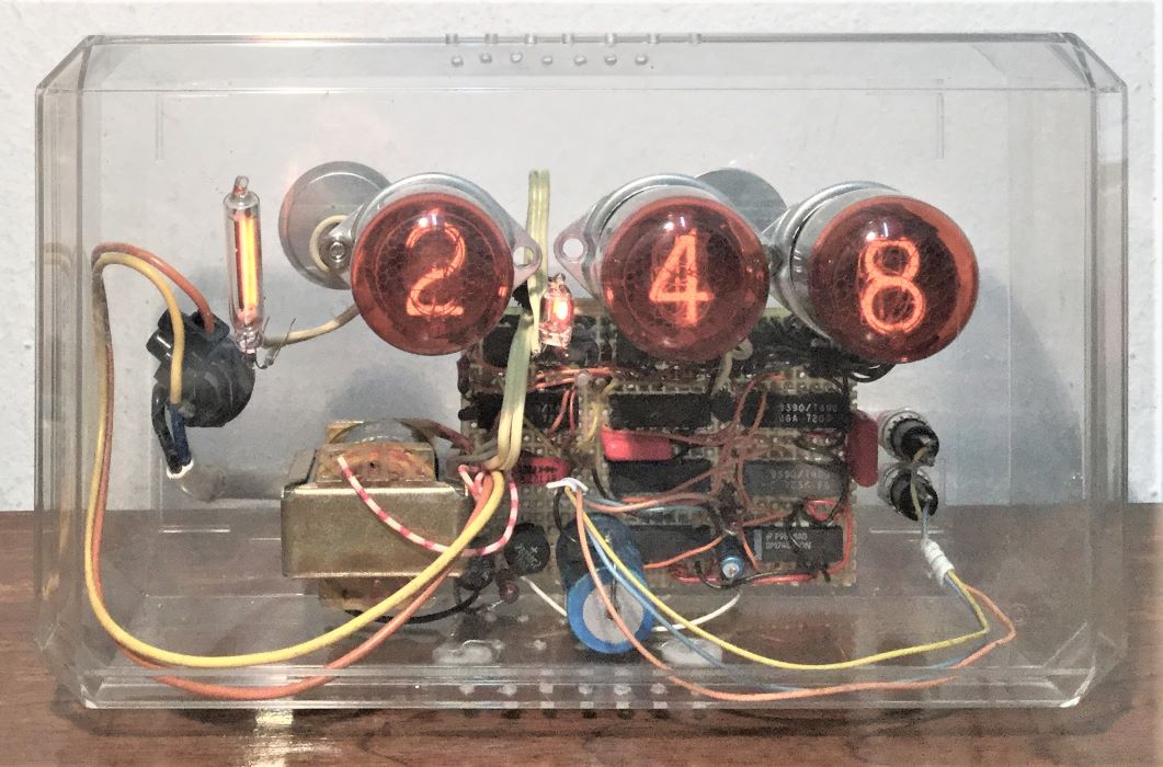
Update january 2017:
I replaced the tens of hours nixie with a similar sized neon bulb as this was the original design idea,
a clock with only three nixies.
Actually the color difference between the neon bulb and nixies is much less noticeable, the camera exaggerates it a lot.
Click on the picture to enlarge:
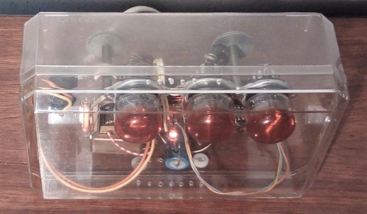
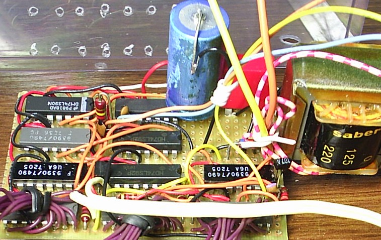
Top view:
This is the clock before mounting in its box, the neon lamp represents tens of hours since I didn't have the larger neon bulb yet.
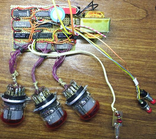
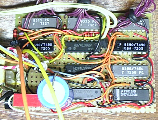
Some integrated circuits are original TTL ICs from early seventies and are labelled with their manufacture date: three 9315 in the top row are dated 7327 (year 73 week 27, June 1973), two 7490 in the second row left and right are dated 7205 (February 1972) in ceramic package and a 7490 in the third row right is labelled 7236 (September 1972) in grey plastic package. They are made by Fairchild, draw around 20mA and get warm.
The 9315 is a Fairchild variant of the standard 7441 TTL decoder and nixie driver, pin compatible and differs only in its overrange outputs (10 to 15). More information at Nixie drivers reference (Brent Hilpert).
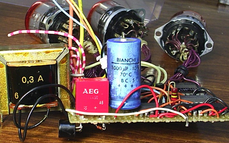
I have reused the current limiting resistors, nixie sockets, wires and a BC107A transistor with gold plated pins. From another old board I got a selenium rectifier AEG model B20C450 and a 1000µF 10V Bianchi capacitor for its power supply.
Like many vintage electronic circuits from that era, the entire circuit is live, uninsulated, directly connected to mains power. This is a simple, cheap and effective way to get the necessary voltage to drive nixie tubes but has the drawback that the circuit cannot be touched in any way while powered or you may get an electric shock. This type of design is not meant for playing or experimenting with circuits, instead it is meant to be built and enclosed in an isolated case before power is applied for the first time.
Having said that, for improved safety the circuit has resistors limiting current from both mains poles that limit the impact of an accidental short or electrical shock. Also once unplugged it does not contain capacitors that could store a dangerous electrical charge.
To probe the circuit you can disconnect diode D3 and resistor R9 to isolate the digital circuit from mains, then it will operate normally however the nixie tubes will not light up.
Important:
TTL parts: 7490 and 7492, 74LS90 and 74LS92, 74L90 and 74L92,
74S90 and 74S92, 74H90 and 74H92, 74ALS90 and 74ALS92 or 74F90 and 74F92.
Circuit updated on August 2014.
View original design (April 2003). Changelog:
- moved resistor R9 to the opposite mains pole to limit current from both poles, improving safety.
- added a low-pass filter (R3 and C6) to the 50Hz signal to filter out
transients and improve time-keeping accuracy.
The entire circuit is live and under dangerous mains voltages, it must be isolated properly and never touch any part of the circuit while plugged.
As a time reference it uses the 50Hz mains frequency. To use only three nixies this clock counts hours up to 12 and displays tens of hours using a neon bulb, resistor R5 has to be selected according to that bulb.
The design can be optimized to save one integrated circuit. The following circuit replaces U7, U8, U9 and U10 in the previous schematic to perform the same function with three instead of four counters, so we have a working nixie clock with just 6 counters.
U9 is a 7492 and if desired can be replaced by a 7493 connecting pin 11 to pin 2, pin 8 to pin 3, pin 11 output to U8 and pin 6 and 7 left open. Like the original schematic TTL parts must be used: 7493, 74LS93, 74L93, 74S93, 74H93, 74ALS93 or 74F93.
For countries with 60Hz mains, both circuits can be adapted: Modifications for 60Hz mains.
Nixie supply voltage is obtained by rectifying mains AC with D3 diode and limiting current with resistors R5, R6, R7, R8 and R9. Rectification is necessary so that only the numerals glow and not the nixie grid or internal wires and current has to be limited because neon once ignited does not limit it by itself. Half-wave rectification reduces by half the time the nixie glows, extending its life with no noticeable flicker.
R6, R7, R8 (and R5 if a nixie is used) resistor values are calculated according to nixie specifications: ZM1020 (Dieter's data archive). 47k with common 12k ½W were the resistors on the original board that I reused, this equates to 95k per tube because the common resistor supports 4 times the current (12k * 4 + 47k). In ZM1020 datasheet page 7 we get that 95k with pulsating 330V supply gives a nominal current of 1mA per tube, the minimum for full glow coverage. Peak current is 2mA ((330 − 142) / 95k).
The voltage drop in the nixie tubes is 170V at turn on (page 2, ignition voltage), 142V while lit (page 4, maintaining voltage with 2mA peak) and 118V when glow extinguishes (page 2, extinguishing voltage).
The 9315/7441 is designed to drive nixie tubes directly, for this reason its outputs handle up to 70V with 2mA (F9315PC at Datasheets360). In normal operation each 9315 has always an active (grounded) output since it lacks the capability to turn off the tubes. With one cathode grounded, the anode voltage will not exceed the nixie ignition voltage of 170V, so that the inactive digits will see no more than 100V (170 − 70), that is below the 118V extinguishing voltage ensuring inactive digits do not glow.
Let's see what happens in the inactive cathodes. From the current vs floating voltage curve in ZM1020 datasheet page 5 we know the nixie weakly pulls them up to the anode voltage with currents in the µA range. 9315 datasheet does not include a similar curve but states a cut-off leakage (Ioh) of 40µA at 55V, because the nixie inactive cathode current is somewhat higher between 50 and 200µA it may pull the voltage slightly higher but very far from the supported 2mA at 70V. This sets the nixie operating point in the nominal operation area, the area to the right of curve N so it will work optimally.
In the event that no output is active (for example if 5V supply voltage is missing) the voltage at the 9315 outputs will reach 70V and leak some current resulting in a dim glow in the nixie. This current will not exceed 1mA, well below the supported 2mA at 70V as per datasheet, thus no risk of damage.
The tens of hours neon lamp is the only one that can be fully off, therefore I use a BF422 high voltage transistor with a voltage rating of 250V. In the off state the bulb anode voltage is 258V (330 minus 72 that drop at common resistor R9), this leaves 8V insufficient to ignite any neon bulb.
Due to the high current drawn by these TTL ICs a transformerless power supply is not suitable. Following strict vintage minimalist style a resistor is enough to adjust the 5V supply voltage, given that current drawn by these TTL ICs is constant enough. It may seem crazy to adjust the supply voltage this way but it works, my clock has been ticking for more than 15 years now. R10 resistor value has to be selected according to circuit current draw and resulting supply voltage with that load. These TTL IC operate between 4.5V and 5.5V, I recommend to adjust it slightly below 5V so that there is margin against power surges. D4 5.6V zener diode together with the fuse in series with R10 protect against overvoltage. In normal operation voltage at D4 is insufficient to make it conduct any current but in an overvoltage event it will absorb most current limiting the voltage until fuse opens.
Some 100nF filter capacitors are recommended from 5V supply to ground distributed across the circuit to filter noise and improve stability.
Nixies are controlled by three 9315 (7441) ICs designed to drive nixie tubes, they contain a decoder to be connected directly to binary counters. In this circuit, minute and hours units are connected to 7490 decade counters and tens of minutes to a 7492 that counts to 5.
Time-keeping is performed by a set of concatenated counters that divide the 50Hz mains frequency down to one-minute pulses. R3 resistor connected to U10 pin 14 brings 50 pulses per second from transformer output to the first counter clock input, R3 together with C6 form a low-pass filter to eliminate transients that could make the clock run faster.
In the original schematic U9 and U10 divide by 5 and 10 respectively counting to 50 and generating a pulse per second on U9 pin 11, and U7 and U8 divide by 6 and 10 respectively counting to 60 so that on U7 pin 8 we have a pulse per minute to drive the minutes counter U6.
In the optimized schematic U9 divides by 12 and U7 and U8 together are a 8 bit
hexadecimal counter that divides by 250, so all three counters divide by 3000. This is
the number of mains voltage swings in one minute, resulting in a pulse per minute to C3.
To divide by 250 counters U7 and U8 reset when their outputs match binary pattern
11111010 (value 250). Diodes D5 to D9 keep U8 MR2 (pin 3) reset input low while any of
the outputs corresponding to the one's in the binary pattern are low. When the counter
reaches 250 both MR1 and MR2 (pin 2 and 3) reset inputs are high and U8 resets, incrementing
U7 that was in its last value so it goes back to zero.
For tens of hour I used the free flip-flop in U5, output from this flip-flop pin 12 controls the tens of hour neon lamp by switching transistor Q2. Flip-flop state flips when it receives a pulse on pin 14 and this happens when the hours units change from 9 to 0 and from 2 to 1 (9 to 10 and 12 to 1 hours), in other words, when hour units are 0 or 1. This is because the way the nixie is wired to the decoder, shifted two places.
Hour units nixie is wired so the relevant values 0 and 1 correspond to binary values 8 and 9 in the 7490 counter, these values activate U4 pin 11 (the most significant bit) and signal the flip-flop to change state through transistor Q1 acting as an inverter, since the flip-flop reacts on the falling edge. Now the tens of hour lamp switches on and off properly and all is left is to have hours count from 12 to 1.
To reset hours from 12 to 1, MS1 and MS2 inputs are activated to reset the counter to value 9 (1 displayed). The tens of hour flip-flop status is input on U4 pin 6 and diodes D1 and D2 implement a logical AND that sets high U4 pin 7 when the counter reaches value 1, so at 13 hours both inputs activate and reset hour to 1. D2 stops the counter to be set at 11 hours, counter value 9.
Finally push button debounce is achieved with capacitors C3, C4 and C5 and a 100k resistor paralleled with MIN+ button. These capacitors block DC voltage and only let through a short pulse when signals change state, effectively mixing them. The 100k resistor keeps capacitors charged so that there is no voltage difference on push buttons terminals and no increment when pushed down, the counters increment cleanly only from pulses from U9 pin 9.
The values of these capacitors were selected experimentally. Excess capacitance (for example 4.7nF) made the counter react on both the rising and falling edge, incrementing twice each cycle. With 470pF it no longer happened and with 4.7pF it still was fine, therefore 47pF was taken as a middle value. Note that when a rising edge occurs, the capacitor is charged and raises the input voltage above the supply voltage, for this reason to minimize adverse effects it is not advisable to use a larger capacitor.
It is possible to modify the original circuit for use in countries with 60Hz mains frequency changing U9 to a 7492 IC and connecting it like U7, C4 capacitor to pin 11 and wire to U8 to pin 8.
Also the optimized circuit can be adapted:
Operation of this circuit is similar to the one for 50Hz mains.
U9 divides by 16 and U7 and U8 together are a 8 bit
hexadecimal counter that divides by 225, so all three counters divide by 3600. This is
the number of mains voltage swings in one minute, resulting in a pulse per minute to C3.
To divide by 225 counters U7 and U8 reset when their outputs match binary pattern
11100001 (value 225). Diodes D5, D6 and D7 keep U7 and U8 reset inputs low while any of
the outputs corresponding to the one's in the binary pattern are low. When the counter
reaches 225 both MR1 and MR2 (pin 2 and 3) reset inputs are high and both counters reset
to zero.
Project completed on October 2007 by Jeroni Paul.
Copyright © 2007 Jeroni Paul.