ARARINHA #1
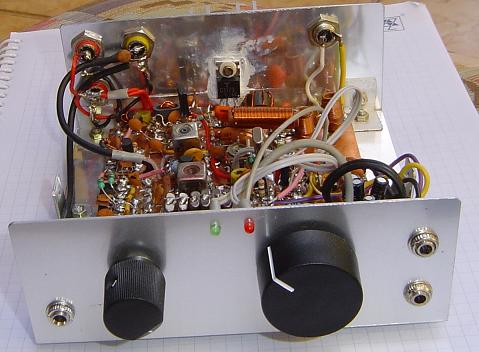
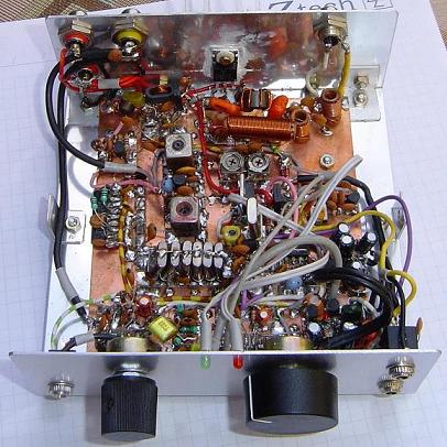
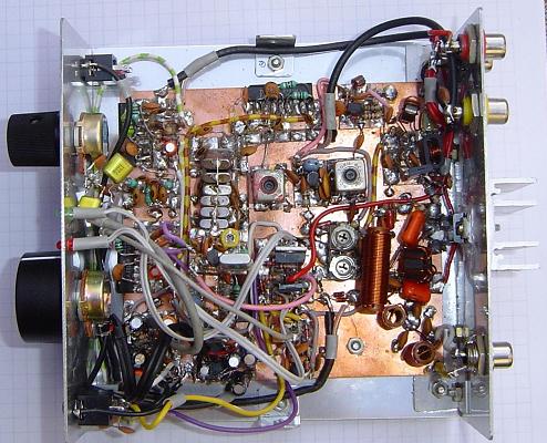
Foto: Fizemos muitas modificações e ainda restaram circuitos inutilizados como a parte de CW. Esta montagem foi um laboratório.
Um transceptor QRP simples de SSB, com 4 Watts de potencia para os 40m.
Depois de montarmos o BITX, repensamos o projeto com circuitos integrados e chegamos a um resultado surpreendente. Com poucos componentes desenvolvemos um projeto simples e eficiente.
Esquema
Funcionamento
RX:
Montamos um front end diferente dos convencionais, mas poderia ser um simples. Como este estava montado aproveitamos.
Para reproduzir ele é necessário que os componentes sejam selecionados em um LC meter e que estejam com 5% de precisão.
A curva de resposta é bastante interessante deste circuito.
Para o amplificador de RF em 7Mhz / mixer empregamos o TA7358, note que o mixer requer muito pouca excitação.
Aqui o mixer mistura o sinal de 7MHz com o do VFO e temos 10MHz na saída.
O filtro ladder a cristal foi empregado um de 6 pólos, mas poderíamos empregar um de 4 pólos.
Para amplificador de FI (10MHz) e mixer / detector empregamos outro TA7358.
O amplificador de áudio emprega um circuito de áudio já consagrado (do BIGODE).
O oscilador VFO é externo e será descrito em outra pagina deste site.
O oscilador BFO é um circuito com 2 transistores 2N3904 que também já foi empregado em outros circuitos nossos.
TX:
O amplificador de microfone é o mesmo do Maritaca.
O modulador balanceado é o TA7358, que não necessita de ajustes.
O filtro de SSB ou ladder é o mesmo da recepção.
O amplificador de FI e segundo mixer é oTA7358. Na saída do TA7358 já temos o sinal de SSB em 7MHz.
Para separa outros sinais indesejáveis temos um filtro especial de alto Q.
O próximo estagio é o driver com um BD139 daí temos o amplificador de potencia com o 2SC1173.
O chaveamento TX/RX é feito por uma chave eletrônica comandada pelo PTT.
Testes
Nos testes conseguimos contatos do Sul do Brasil PY3 até PY6 Bahia.
Devido ao baixo ganho do receptor resolvemos montar o ARARINHA #2
ARARINHA #1
Picture: We made several mods, in the box are assembled and dont removed some modules from the CW keying. This TRX was a labor.
A simple transceiver QRP of SSB, with 4 Watts of harnesses for 40m
After building the BITX, we rethink the project with integrated circuits and arrive at a surprising result. With few components we develop a simple and efficient transceiver.
Schematic
Functioning
RX:
We build one front end different of the conventional, but it could be a simple
ones. We use to advantage as this was mounted. To reproduce it is necessary
that the components are selected in a LC meter they need to be within 5% of
precision
For the amplifier of RF in 7 MHz/ mixer we use the TA7358, note this mixer requires little excitement .Here the mixer mixes the signal of 7MHz with the VFO and we have 10MHz in the exit.
The ladder crystal filter used had 6 poles, but we could use one of 4 poles.
For IF amplifier (10MHz) and to mixer/detector we use another TA7358.
In the audio amplifier we use a consecrated circuit.
The VFO oscillator is external and will be described in another page of this site.
The BFO oscillator is a circuit with 2 transistors 2N3904 that also already was used in other ours circuits.
TX:
The microphone amplifier is the same of the Maritaca.
The balanced modulator is TA7358, that it does not need adjustments.
The filter of SSB or ladder filter is the same of the reception.
The amplifier of IF and mixer is theTA7358.
In order to separate other signals undesirable we have a special high Q filter.
The next circuit is the driver with a BD139 from there we have the power amplifier with 2SC1173.
Keying TX/RX is made by an electronic key commanded by the PTT.
Tests
In the tests we made QSOs contacts to the South of Brazil PY3 until PY6 Bahia.
Because to the low gain of the receiver we decide to build the ARARINHA #2
73 de PY2OHH Miguel