THE CANARINHO
After the second crystal group buy for the CW QRP calling frequencies, very few of the friends used the crystals.
Canarinho is the name that in Brazil means a bird with a phenomenal warbling. Nothing is better for a xtal TX name...
So we decided to design a TX to fill this hole...
A transmitter with a lone transistor rendering a maximum in power, easy to build and with low parts count: a QRP !
We started to build the TEIMOSO by Gomes PY2MG, that matched its name... it arrived to deliver 2.5W, but it shyly (teimosamente) did not admit a change of crystal or transistor, after some time we gave up... in the end what we looked for was something easier to build or replicate.
We returned to the charge with the old Colpitts oscillator, we started with an emitter resistor of 47 Ohms, changing (lowering) the collector-base resistor we changed the power till the transistor refused to oscillate.
We replaced the resistor which heated a lot (heat sinking both DC and RF!) with a 22µH Sontag (blue) inductor. We increased the power.
We recorded that with transistor of different Beta (gain) we achieved to extract a maximum of power varying the base-collector resistor (10K in the schematic).
Beside that we can change the transistor... remembering that with low Beta (gain) the transistor needs a bigger bias current and that we are limited by the current flowing through the crystal, the bigger the beta the better.
In the tests we got
|
TRANSISTOR |
RESISTOR min. base - collector |
Max. POWER |
|
COMMON BD139
|
2k2 |
1W |
|
BD139 with bigger beta |
4k7 |
1,2W |
|
2N3904 |
15k |
0,25W |
|
2SC2078 |
2k2 |
1,2W |
|
7 x 2N3904 with 1R5 in the emitter |
2k2 |
1,8W |
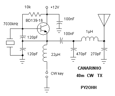
Our schematic :

Simple version Canarinho
We decided to keep the base-collector resistor in 10K limiting the power output to 1 Watt.
The pi tank capacitor value on the antenna side (270pF) showed itself critic as it worked well with a resistive load, but it stopped to oscillate with an antenna - due to the cable capacitance - we lowered it from 470pF to 270pF solving the problem.
In the CANARINHO simple version we have only the TX, keyed directly by the CW key. Building it this way we have a current of about 180mA in the key, but it is no good because it burns the key contacts in little use time.
Second version :

CANARINHO Version 2
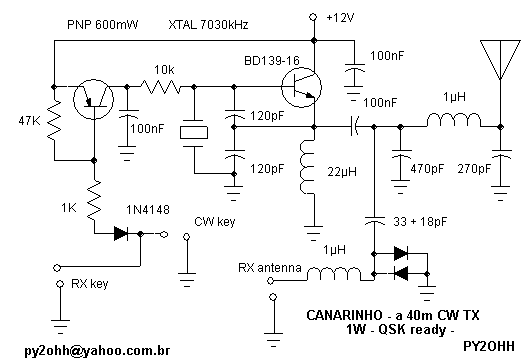
In the version 2 we added an electronic switch, with the incorporation of a garden type PNP transistor (BC556, 557, 558, 559, 560) so we lower the keying current at least 100 times.
Version 3

CANARINHO version 3
In this version the CANARINHO works QSK and can be directly connected to a receiver without damaging it.
We operate with a R1000 receiver, the signal drives the S meter to full deflection forcing to key in about 80dB attenuation levels, when we operate with a homemade receiver we do not have this problem, because we can also key the receiver. We did not study the R1000 schematic to see if it has this option (mute).
Tests :
With a dummy load integrated by two metal-film type 100R resistors in parallel and a RF probe, we measured the RF Vp. We have 10V (Vp) peak voltage.
Power (W) = Vp * Vp / (2 * R (load) ) = 10 * 10 / 2 * 50 = 1 W
Operation :
The Tx went out in 7029KHz so we worked with a lot of comfort :
PY4TW RIC BARBACENA
PY2EYE NILSON SOROCABA
PY2IAX VALD JARDINOPOLIS
73 a todos (everybody)
PY2OHH - Miguel
São Bernardo do Campo - SP
[email protected]
O CANARINHO
Depois do segundo mutirão de compra de cristais para as freqüências de operação CW, poucos colegas utilizaram os cristais.
Canarinho é o nome que lembra o Brasil e um pássaro que tem um gorjeio fenomenal. Nada melhor para o nome de um TX a xtal.
Assim resolvemos fazer um TX para preencher esta lacuna ...
Um transmissor com um único transistor que pudesse render um máximo de potência, fosse fácil de montar e com poucas peças : um QRP !
Partimos para montar o TEIMOSO do PY2MG o Gomes, que fez juz ao nome ... chegou a sair 2,5W, mas teimosamente não admitia a troca de cristal ou transistor, depois de algum tempo desistimos... afinal o que buscávamos era algo mais fácil para montar ou reproduzir.
Voltamos a carga com o velho oscilador Colpits, iniciamos com um resistor de 47 Ohms no emissor, alterando (diminuindo) o resistor de coletor base alterávamos a potência até o transistor parar de oscilar.
Substituímos o resistor que esquentava muito (dissipando CC e RF !) por um indutor da Sontag (azul) de 22µH. Aumentamos a potência.
Constatamos que mesmo com transistores de Beta (ganho) diferentes conseguíamos extrair o máximo de potência variando o resistor de base-coletor (10k no esquema).
Alem disso podemos mudar o transistor ... lembrando que com baixo Beta (ganho) o transistor necessita de maior corrente de excitação e estamos limitados pela corrente que passa pelo Xtal, desta forma quanto maior o beta melhor.
Nos testes tivemos
|
TRANSISTOR |
RESISTOR min. base - coletor |
POTENCIA máx. |
|
BD139 COMUM |
2k2 |
1W |
|
BD139 com maior beta |
4k7 |
1,2W |
|
2N3904 |
15k |
0,25W |
|
2SC2078 |
2k2 |
1,2W |
|
7 x 2N3904 com 1R5 no emissor |
2k2 |
1,8W |
Nosso esquema :

Canarinho versão simples
Resolvemos manter o resistor base coletor em 10k limitando a potência de saída para 1 Watt.
O valor do capacitor do tanque pi, lado da antena (270pF), mostrou-se critico pois com carga resistiva ele operava bem, mas com antena parava de oscilar - devido a capacitância do cabo - reduzimos de 470pF para 270pF solucionando o problema.
O CANARINHO versão simples, temos somente o TX, operado diretamente pela chave de CW. Montando assim temos uma corrente de cerca de 180mA na chave, o que não é bom pois carboniza o manipulador com pouco tempo de uso.
Segunda Versão :

CANARINHO Versão 2
Na versão 2 incorporamos uma chave eletrônica, com a inclusão de um transistor PNP de uso geral (BC556, 557, 558, 559, 560) assim diminuímos a corrente de chaveamento no mínimo 100 vezes.
Versão 3

CANARINHO versão 3
Nesta versão o CANARINHO opera QSK podendo ser ligado diretamente a um receptor sem danifica-lo.
Operamos com um receptor R1000, o sinal vai muito alem do S meter obrigando chavear para 80db de atenuação, quando operamos com receptor caseiro não temos este problema, pois podemos chavear o receptor também. Não estudamos o esquema do R1000 para ver se ele tem esta função (mute).
Testes :
Com uma carga fantasma composta por dois resistores de 100R tipo metal-filme em paralelo, mais uma ponta para RF, medimos a tensão de RF Vp. Estamos com 10V (Vp) de pico
Potência (W) = Vp * Vp / (2 * R (de carga) ) = 10 * 10 / 2 * 50 = 1 W
Operando :
O Tx saiu em 7029kHz assim trabalhamos com muita folga :
PY4TW RIC BARBACENA
PY2EYE NILSON SOROCABA
PY2IAX VALD JARDINOPOLIS
73 a todos
PY2OHH - Miguel
São Bernardo do Campo - SP
[email protected]