GOITACAS
TRX 40m - Rx DC - Tx 5W - VXO 6990 -7080kHz
I was still studying some RF application of 74HC4066 IC, I decided to made a transceiver with a little more power 5W.
In the last project with the 74HC4066, it it was acting as to mixer, buffer, oscillator VXO and driver in the Tx. In order to increase the power, I decide to substitute the VXO which uses an analogic gate of the 74HC4066, for a VXO using a BJT transistor. Now the two remaining analogic gates are in parallel circuit.
Practically the whole of this project is the same of the CAIAPO project, the main alteration was really in the drive when we planned to give more power.
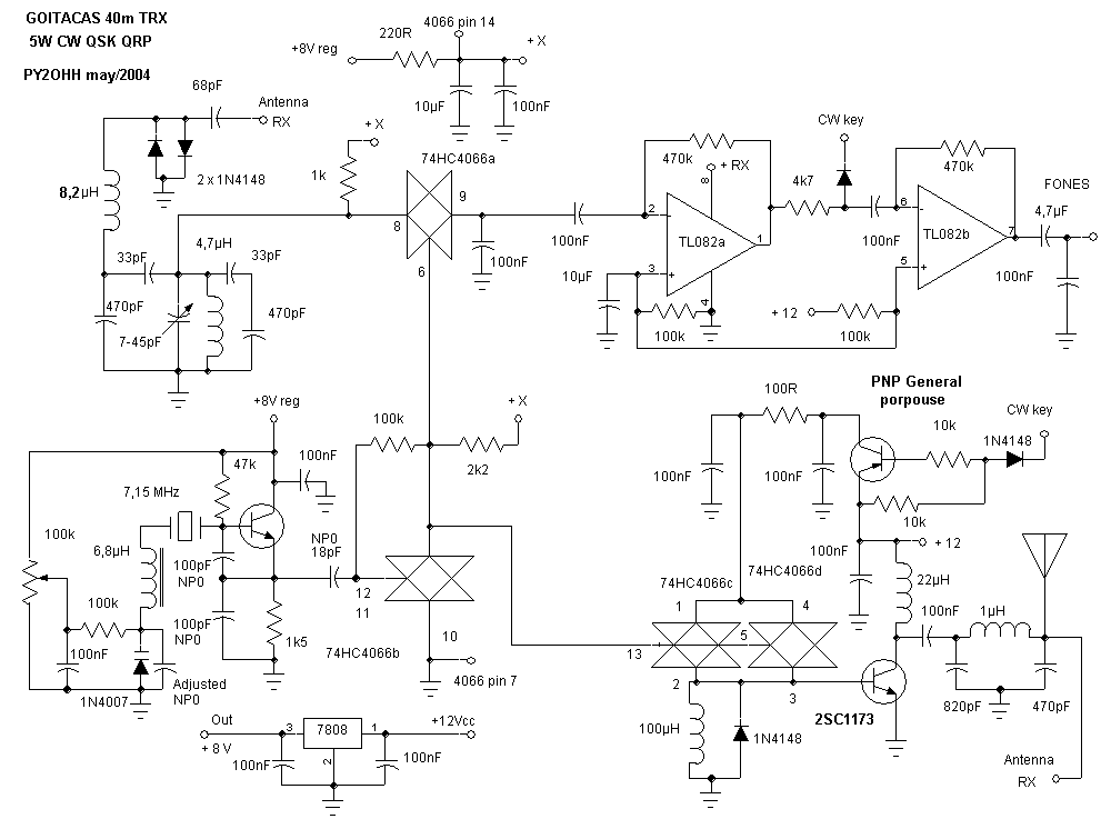
The schematic
Project Description of the circuit
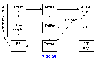
The Receiver
Key T/R (automatic coupler) is a band pass filter, where the reactance of the capacitor and inductor will be near 400 Ohms at the frequency of the filter. Signals of major intensity are limited (cut) in 0.7V by the diodes 1N4148.
The Front End (pass band filter) was calculated for 200kHz of range, the spread sheet of calculations can be found in the area of utilities of this site.
The VXO is based on our traditional Colpitts project with a bipolar transistor NPN like 2N3904 (BC547B, BC548B, 2N2222) using a ceramic resonator of 7150kHz. More details in this area of the site in VFO Colpitts .
Buffer and Mixer : in these functions we use two analogic gates of the 74HC4066. As to mixer it presents impressive results indeed simplicity, and as buffer it perfectly isolates the VXO from the following circuits.
Audio amplifier is our traditional one, uses a double operational amplifier IC where the TL082 functions perfectly or LM358 and LM1458 or many tested others. Good results for CW listenning, with a very simple circuit.
The transmitter
VXO and Buffer see above.
For a driver we use here two analogic gates of the 74HC4066 paralleled, giving therefore a bigger drive for the PA, this differentiates it of project CAIAPO. We use a resistance of 100R in the collector of transistor PNP of key T/R for to control the power (drive) .
In the PA we use the same configuration of the CAIAPO but we got 5W of power of output as planned. In the PI tank we use an molded commercial inductor of 1µH.
Key T/R we use a keying of CC traditional. The transistor is a general purpose PNP (BC557, BC558). And we ground the audio during transmission done by a diode 1N4148 placed between the two operational amplifiers.
Assembly
We use the same described methods like CAIAPO project, it may acessed in this area of the site.
Results
We made a lot of QSOs with many stations in the brazilian northeast (up to 3000Km), Argentina and Uruguay. All with compliments the signals quality.
If someone intends to assembly this tranceiver we desire you good luck and in case that you have any doubt on the project, assembly or acquisition of material, we are QRV to help.
GOITACAS
TRX 40m - Rx DC - Tx 5W - VXO 6990 -7080kHz
Ainda estudando o circuito integrado 74HC4066 resolvemos montar um transceptor com um pouco mais de potência.
No último circuito com o 74HC4066, ele estava atuando como mixer, buffer, oscilador VXO e driver no Tx. Para aumentar a potência de excitação resolvemos substituir o VXO com uma porta do 74HC4066 por um transistor comum e duplicar a potência de excitação utilizando as duas portas analógicas restantes do 74HC4066 ligadas em paralelo
O circuito VXO é o nosso tradicional com BC547B ou BC548B ou 2N3904 trabalhando com ressonador cerâmico e diodo varicap (1N4007) na sintonia.
Praticamente o circuito é semelhante ao do CAIAPO, o rendimento do receptor também foi igual e a alteração principal foi realmente na excitação onde conseguimos fornecer maior potência ao amplificador final de RF (PA).
Esquema
Descrição do circuito
Receptor
Chave T/R (automatic coupler) trata-se de um filtro passa faixa, onde as reatancias do capacitor e indutor tem um valor igual e próximo de 400 Ohms na freqüência do filtro. Sinais de maior intensidade são limitados (recortados) em 0,7V pelos diodos 1N4148.
Front End (filtro passa faixa) foi calculado para 200kHz de passagem, a planilha de calculo pode ser encontrada na área de utilidades deste site.
VXO baseia-se no nosso tradicional projeto Colpitts com um transistor NPN bipolar tipo 2N3904 (BC547B, BC548B, 2N2222) em conjunto com um ressonador cerâmico de 7150kHz. Maiores detalhes nesta mesma área do site em VFO Colpitts.
Buffer e Mixer nestas funções utilizamos duas portas analógicas do 74HC4066. Como mixer apresenta um resultado impressionante pela simplicidade, e como buffer isola perfeitamente o VXO dos circuitos seguintes.
Amplificador de áudio é o nosso tradicional, utilizamos um CI amplificador operacional duplo onde funciona perfeitamente o TL082, LM358, LM1458 entre muitos outros testados. Apresenta um ótimo resultado para CW, com um circuito muito simples.
Transmissor
VXO e Buffer descritos acima.
Driver utilizamos aqui duas portas analógicas do 74HC4066 em paralelo, dando portanto uma excitação maior para o PA, o que diferencia do projeto CAIAPO. A limitação de excitação esta no resistor de 100R no coletor do transistor PNP da chave T / R.
PA utilizamos a mesma configuração do CAIAPO mas obtivemos 5W de potência de saída como planejado. No tanque em PI utilizamos um indutor de 1µH moldado da Sontag comercial.
Chave T / R utilizamos um chaveamento de CC tradicional. O transistor utilizado é um de uso geral PNP (BC557, BC558). Ainda aterramos o áudio durante a transmissão via um diodo 1N4148 ligado entre os dois amplificadores operacionais.
Montagem
Utilizamos os mesmos métodos descritos no projeto CAIAPO, que estão nesta mesma área do site.
Resultados
Mantivemos QSOs com varias estações do Nordeste brasileiro, da Argentina e Uruguai. Todos com elogios a qualidade dos sinais.
A todos que pretenderem montar desejamos boa sorte e caso tiverem qualquer dúvida quer de projeto, montagem ou aquisição de material, estaremos QRV.
73 de PY2OHH Miguel