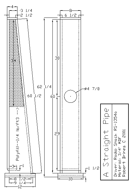
This project was conceived as a response to the Voigt Pipe found elsewhere. It is a straight pipe based on Martin King's Mass-Loaded TQWT technique. Designed specifically for the Radio Shack 40-1354a (unfortunately out of print) wide-range driver, it should accept any 5 1/4" driver with a fs of 50-60 and moderate Qts (0.3 - 0.5). For a larger driver with the same fs, scale up the cross-section by the Sd of the driver.
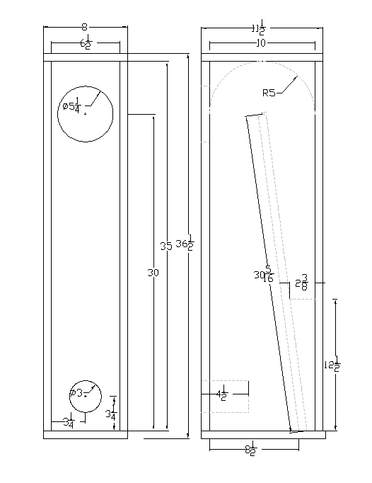
The internal dimensions are determined so that the throat area is equal to the driver Sd and the mouth area equal to 4 times Sd. I think that this produces the best compromise between increased horn loading at f3 and the straightest curve between F1 and F5. The depth is increased by 1/2" to allow for the vinyl tile used as internal damping.
The cabinet is built of 3/4"x12"x6' MDF shelving. To damp the cabinet, all internal surfaces are covered with vinyl tile glued down with vinyl mastic. To damp any reflections back through the driver, a 6" x 12" pad of 1/2" yellow Fiberglas� is placed directly behind the driver. Finally, the cabinet is lightly stuffed with polyfill, from the top down to just below the level of the driver.
>One can argue that this design could use some bracing. I don't think that bracing is warranted because of the modest SPL levels expected. If you must, I would suggest shelf braces.
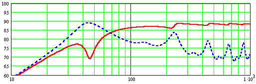
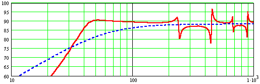
Modeled SPL after stuffing.
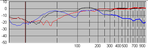
Port output (blue) and driver output after stuffing.
Construction Details:
These instructions are intended for a novice who has never attempted this kind of construction. It is overly detailed for anyone even modestly familiar with speaker building, but someone might benefit for the details.
This project is designed to be built with hand tools using three 3/4"x12"x6' MDF shelves each cabinet. The cabinet is constructed entirely of butt joints. Miter, dado and tongue and groove joints are just not realistic with hand tools. (There is a tool called a dado plane which can be used to.... Forget it!) Therefore, the panel layout is arranged to make maximum use of the factory edges of the MDF shelving for the glue joints. Only the back panel needs to be finished on two edges.
The panels are glued and screwed with yellow PVA glue and 1 1/4" coarse-thread drywall screws. Screws are run through the face of the MDF panels into the edge of the joining panels. Screws into the edge of MDF provide no real mechanical strength. They are adequate to provide pressure to the joint while the glue sets, but that's all. After the glue sets, I remove the screws and plug the holes with light-weight spackling. To assure proper pull-up of the joints and to prevent splitting, drill 5/64" pilot holes the full depth of the screw, and then drill 1/8" clearance all the way through the panel. I put screws on 6" centers.
The Back Panel
Mark the width of the back and draw a cut line the length of the board. Cut the back to width, leaving enough material for finishing. Put the cut off piece between two new shelves, square the edges and clamp both ends. Put the back between the shelves, align the cut line with the top edge of one of the shelves and clamp both ends. Plane the back down flush with the shelves. It is critical to the final fit that the planed edge be straight and square. Cut the back to length plus 1/4" extra. Save the scrap piece. It will be used for the port block, and as a spacer during gluing.
Truing the back panel
The Baffle Board
Cut the baffle to length with a little left over for finishing at the top. Cut the width with a little left over at both sides. Draw two construction lines marking the outside edges of the side panels. These lines are critical -- get them right. Mark this side "Inside". Make the driver cutout . Finally, put a 3/4" round-over on the outside bottom edge (See Minimum Tools).
The Side Panels
Cut the sides from a single piece of shelving. Mark the length of a side, The mark the top and bottom width and draw a cut line. Continue the cut line the full length of the board. Flip the board end for end and repeat the procedure. Saw the sides out, leaving enough material for finishing. Cut off the tops, leaving a little material for finishing. NOTE: You now have two panels with the cut line draw on the inside of one and the outside of the other. Pick one panel and mark the cut line on the opposite side. Draw a line 1" up from the bottom on each panel for alignment of the baffle.
Assembly
NOTE: The baffle is glued to the rest of the cabinet AFTER the cabinets is lined and stuffed.
Screw the cabinet together. Don't even think of going for the glue bottle until everything dry-fits together properly. Place the baffle on your work bench inside up. Stand the side panels up on the baffle. Place that piece of scrap you saved from cutting the back panel :-) between the sides near the bottom. This will assure that everything will be square. Align the 1" lines on the sides with the bottom of the baffle and clamp the sides to the scrap with a bar clamp. Now the same procedure at the other end. Use the port block as a spacer between the side for alignment. Place the port block between the sides and clamp the sides with a bar clamp. Check that everything is lined up -- the sides are on the construction lines on the baffle and the 1" lines line up with the bottom of the baffle. Check it again! Slide the back panel between the sides. Support the back at the cut lines on the sides with C-clamps. Align the inside edge of the back with the bottom of the sides. Drill and set the first screw at the bottom and the last screw at the top. Gently roll the side-back-scrap assembly on its side. Check the alignment of the back and side at the middle. Drill and set the middle screw. Now drill and set the rest of the screws on this edge. Flip the assembly over and set the rest of the screws on the other edge of the back.
Checking Alignment
Once the back and sides are screwed together, you can remove all of the clamps. Place the cabinet on its back and screw down the baffle. No more admonitions to check the alignment. Once you are sure everything fits together properly, place the cabinet on its side, remove the side facing up. Sand down any material raised around the screw hole to help make the joint tight. Run a 1/4 bead of glue down the edge of the back. Spread it with a finger, making sure the entire edge is wet. Replace the side and screw it down. Flip the cabinet over and repeat with the other side.
Once the glue sets, plane the bottom of the back flush with the sides, and plane all four panels at the top down to the cut marks. Cut a piece of MDF for the top, glue and screw it to the sides and back only. Screw it to the baffle for alignment, but try to keep glue out of the top/baffle joint at this time.
Damping
I decided to line the cabined with vinyl tile to quiet the panels. I bought some (20!) 12" x 12" vinyl floor tiles. I cut them to to fit on all four sides of the cabinet. Mask all of the edges and the baffle that will be glued later. This is important! Now apply vinyl floor mastic to the insides of the cabinet (and the baffle) with a notched trowel. Set the tiles and let the whole thing set overnight. I am not sold on the need for panel damping in a low power speaker, but it can't hurt.
Lining and Stuffing:
>(Since I've done all of the work, you can go to the bottom of this section and install the recommended stuffing.)
>Make the piece for the top of the port. I tried several lengths (ok, widths) during the stuffing trials. 6 1/2" x 3" is the best size. Put a 3/4" round-over on one long edge. This piece is wedged in place during trials.
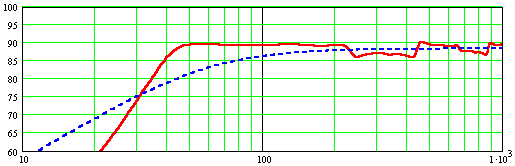
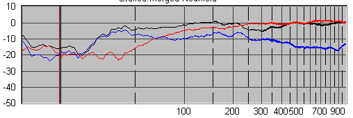
First, I took some SPL measurements of the bare pipe. The black line is the combined output, the red line is the driver output and the blue line is the port output. Below that is the modeled combined output.
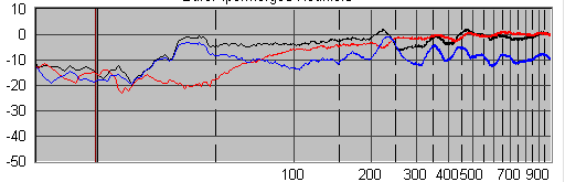
Next, I lined all four sides of the cabinet with yellow Fiberglas�. The results are:
It's over-damped! I'm going to have to remove some of the lining and retest.
Ok. Removed all of the Fiberglas� except for a 6" x 12" piece directly behind the driver. I played with several diferent packing densities and tried both Miraflex� and polyfill. The bottom line is Miraflex� and polyfill are one-for-one replaceable. Also, packing density is not critical, within reason. However, it is EXTREMELY important that the stuffing does not extend more than 2" below the driver, or bass extension is rapidly lost. The final stuffing configuration is moderately firmly pack polyfill (simply because I tried the Miraflex� first, and there is no need to change back), from the top to 2" below the driver:
Glue and screw the baffle to the sides and top. Glue in the port piece. Screws are not necessary, but make sure the fit is air tight.
(I put a 3/4" round-over on all edges of the cabinet. This is pretty much for cosmetics only, so put what ever edge treatment you want. However, do the edge treatment BEFORE you proceed!)
Build the plinth for the bottom. I decided on two thicknesses of MDF, cut as per the drawing. Glue and screw the one piece of MDF to the bottom of the pipe, then glue and screw the second piece of MDF to the first. True edges and apply the edge treatment of you choice. I put a 1/2" chamfer on the edges, just because.
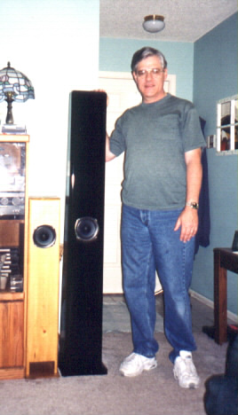
The cabinet is now complete. Mount the driver, the input cup or binding posts, wire it up and give it a listen. Nice, no?
Finishing
Apply the finish of your choice. Veneer it, paint it, whatever. I'm going to do a black gloss finish. Not having any experience with finishing MDF, this part of the project turned into a real adventure.
The single biggest mistake I made was to try to apply primer with a brush. Two things happen. One, you get too much primer around the base and port. Also, the primer will not level, so there will be massive brush marks in the dried primer. Second, because of one above, it takes forever for the primer to dry, and don't think about sanding until the primer is really dry. Then, you need to sand virtually all of the primer off, which takes forever and clogs all of your sandpaper, because you didn't let it dry long enough.
Get primer in spray cans! Just make sure it is wood primer. Metal primer will be worse than useless. Put a couple of light coats on the raw edges of the panels. If there are any visible imperfections, fill them NOW with light weight spackling. Sand it off (150 grit) and apply some more. Repeat until there are no more imperfections, using 220 grit paper. Spray the entire cabinet with primer. Fill, sand, spray, repeat. Once everything is smooth, spray the entire cabinet and sand smooth with 320 grit. Spray the color coat. you're done.

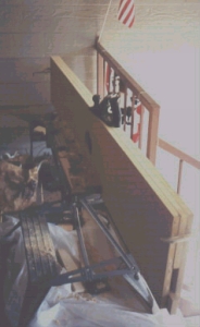
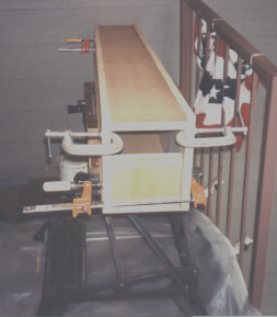
Pipes in the paint shop.
Baffle Step Correction
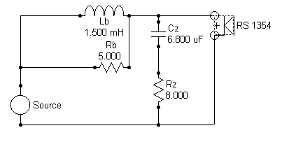
These pipes, like all tall, thin cabinets suffers suffers from baffle step loss. In the far field, frequencies below 800hz are reduced by several db's. This makes the speaker sound thin, with little bass. One solution is to place the speakers flush against the back wall. This sort-of works, but is not good for imaging. The best solution is to install a baffle step correction circuit. Put a zobel (6.8uF cap in series with 8ohm resistor) in parallel with the driver. Put a 1.5mH iron core inductor in parallel with a 5 ohm resistor in series with driver. Adjust the value of this resistor to balance the sound of the speaker.
So, you really want to do a folded pipe. OK. Try this. It should perform exactly like my straight pipe, however, be aware that I have not built or tested this design. Yow may have to adjust the port length, depending on the driver you actually use. Start out with a length of 2" and increase it as necessary to get the results you want.