'BERNIE' THE ROBOT BUTLER
Back in 1997, when the 89C2051 was brand-spanking new, I decided to have a go at building my own robot pet. My design philosophy was very simple - to build it as cheaply as possible with as much functionality as possible. Since I had set a budget of around $100, I set about getting the parts as cheaply as possible.
Structural Frame:
Two things greatly assisted me in the construction -
1.) I found some sheet-aluminum from an old construction site, while only 0.5mm thick was thought to be useable.
2.) All of the wheels - along most of the gearing -came from an old video recorder that my folks had just junked (it was already second-hand by the time we bought it, so it was pretty old).
The tricycle frame was the simplest setup that I could think of - except maybe a flying (hovering?) robot!
Robot primary sensor:
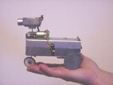
The next thing I had to do, was give the robot a set of 'eyes'. Since C.C.D.'s were expensive (just the camera would've easily broken my budget ;) It was decided - at $10 total cost - that an ultrasonic sensor would give our little robot 'sight'. Since I thought it would be useful (and cool) to make the robot 'look' (scan) from left-to-right-left-and-so-on, a medium-torque motor was installed on the robot's shoulder (see Fig. 2 below). It would allow the robot to 'sweep' over a 180 degree arc while picking up tissue-box sized objects from a distance of 500 mm away. A hall-effect sensor (not shown below) was to indicate 'center' position ie: when the robot's head was facing dead-ahead. The scanning limits were programmed in the 89C4051.
Drive system:
It was decided that a simple high-torque motor would be used - coupled with a single 1Amp-rated power transistor to provide P.W.M. (Pulse Width Modulation) control of the motor speed. One problem with this arrangement, however, was that the motor can only go forward, not reverse - but the sonar and the tricycle steering were to help make up for any shortcoming.
Steering system:
The steering system is basically almost identical to the sonar head drive, except that the arc movement was smaller (about 100 degrees to keep the mechanical loading down). The steering limits were programmed in the 89C4051.
Distance sensing:
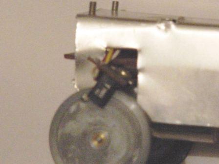
This was accomplished by drilling a hole in the outer rim of one of the drive wheels and fitting an optical slot-sensor. It gave out a signal pulse every time the robot traveled 140mm. This arrangement allowed the MCU (brain) to keep a rough track on roughly how long a journey from A to B was going to take - along with sonar input (ie: terrain following mode).
Robot Image Gallery:
|
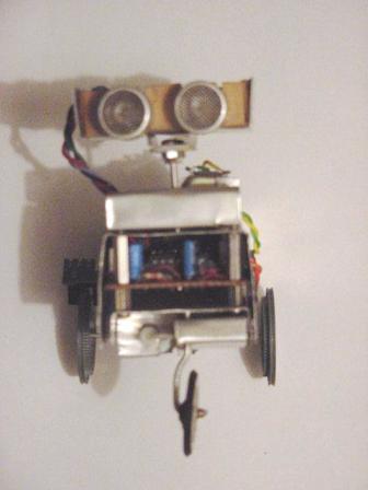
Figure 1.) Frontal View |
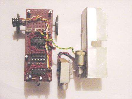
Figure 2.) Robot Disassembly... with main control board exposed. The motor on the 'shoulder' of the robot allows the head to traverse for a sonar sweep (peek!) |
|
|
|
|
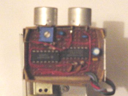
Figure 3.) Robot Sonar module (head) view 4093 IC for the transmitter 4069 IC for the receiver VR1 adjusts the carrier frequency (sorry for the blurry photo!). |
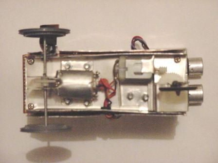
Figure 4.) The underbelly of the Beast! The motor on the left is (obviously) the main drive motor while the other motor is for tricycle-wheel steering. |
|
|
|
|
Figure 5.) Close-up of the Rear Port wheel and optical distance sensor (encoder). note the small hole at the edge of the rim used as an optical marker. |
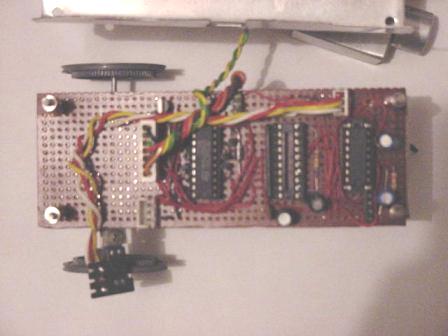
Figure 6.) Close-up of the main control board. Parts include: Socket for the 'brains' - AT89C4051 4093 Hex schmitt trigger for sensor conditioning L293E Dual H-Bridge Driver scan/steer motors 2N6725 Power transistor for P.W.M. control of the main drive motor. |
 |
|