Sample Calculations
|
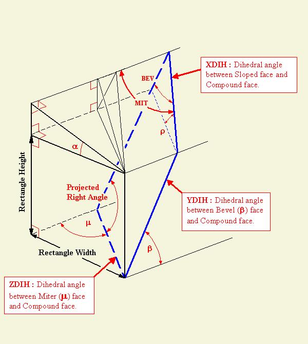
The program solves the miter, dihedral and blade angles required to make a cut along a sloped face that conforms to the specified miter and bevel angles on the rectangular portion of a timber.
The calculation may be repeated for slopes (if any) on the remaining faces.
Some examples involving special cases are given below. The same reference values are used for each calculation, to demonstrate how much information this program can extract from the same basic data. |
|
SPECIAL CASE: XDIH = 90 Degrees
Reference Data 9/12, 7¼ /12, 90° Total Deck Angle 9/12 Side Hip Rafter Peaks meet at Center Post |
|
ENTER:
Miter Angle μ = 48.32249 (R4P) Bevel Angle β = 64.80315 (90 - R1) Slope Angle of Cross-Section α = 27.85609 (C5) Width of Rectangular Face = 4 Height of Rectangular Face = 8 RETURNS to five decimal places: Miter Angle on Sloped Face MIT = 44.80175 (P2) Angles on Projected Triangle Projected 90 - α BEV = 53.13010 (90 - SS) Projected α ρ = 20.42558 (P6) Angles on Parallelogram (Supplementary pair of projected Right Angles) 106.44432 , 73.55568 (90 ± R5P) Dihedral Angle along Sloped Face XDIH = 90, the angle between the Roof Plane and the plumb plane representing the side face of a Common Rafter Blade Angle = Zero Dihedral Angle along Line of β YDIH = 51.14663 (90 ± DD) Blade Angle = 38.85337 (DD) Dihedral Angle along Line of μ ZDIH = 109.36219 (90 ± A5P) Blade Angle = 19.36219 (A5P) Cross-Section Triangle Dimensions: the dimensions of the triangle created by the Backing Angle. Rise = 2.11397 Run = 4 Slope = 4.52425 Projected Triangle Dimensions: the triangle created by the Backing Angle projected to the compound face. projected Rise to Line of β = 2.33626 * projected Run to Line of μ = 5.35547 * Length along Slope of MIT = 6.42051 * Equal to corresponding Trapezoid Edges Parallel Trapezoid Edges: the trapezoid edges are the dimensions of the faces adjacent to one another at the Hip Rafter peaks. Minimum Height = 8.84124 Maximum Height = 8.84124 + 2.33626 = 11.17750 |
|
SPECIAL CASE: XDIH = 90 Degrees
Reference Data 9/12, 7¼ /12, 90° Total Deck Angle 9/12 Side Housing Chamfer for Jack Rafter meets Valley |
|
Same angular values entered as above, with a different interpretation of the results.
In this example, the triangle of the square cut, as seen in section, is projected to the plumb face of the rafter.
Substitute values from a table of Cognate Square Cut Angles may be used in place of the angles given below.
ENTER: Miter Angle μ = 48.32249 (R4P) Bevel Angle β = 64.80315 (90 - R1) Slope Angle of Cross-Section α = 27.85609 (C5) Width of Rectangular Face = 1 , the housing depth perpendicular to the mortised face. Height of Rectangular Face = N/A, enter Zero. RETURNS to five decimal places: Miter Angle on Sloped Face: the miter angle of the rafter face on the roof plane. MIT = 44.80175 (P2) Angles on Projected Triangle Projected 90 - α : bevel angle on the adjacent face (plumb face) of the rafter. BEV = 53.13010 (90 - SS) Projected α ρ = 20.42558 (P6) Angles on Parallelogram (Supplementary pair of projected Right Angles) 106.44432 (90 + R5P) Dihedral Angle along Sloped Face XDIH = 90, the angle between adjacent Jack Rafter faces , Blade Angle = Zero Dihedral Angle along Line of β YDIH = 51.14663 (90 ± DD) Blade Angle = 38.85337 (DD) Dihedral Angle along Line of μ ZDIH = 109.36219 (90 ± A5P) Blade Angle = 19.36219 (A5P) Cross-Section Triangle Dimensions: the chamfer or square cut, as seen in section. Rise = .52849 Run = 1 Slope = 1.13106 Projected Triangle Dimensions: the chamfer projected to the plumb face of the Jack rafter. projected Rise to Line of β = .58407 projected Run to Line of μ = 1.33887 Length along Slope of MIT = 1.60513 |
|
SPECIAL CASE: α = Zero
Reference Data 9/12, 7¼ /12, 90° Total Deck Angle 9/12 Side Jack Rafter meets Valley Compound Angle and Blade Angle Calculation |
|
ENTER:
Miter Angle μ = 44.80175 (P2) Bevel Angle β = 53.13010 (90 - SS) Slope Angle of Cross-Section α = Zero Width of Rectangular Face = 6 Height of Rectangular Face = 6 RETURNS to five decimal places: Miter Angle on Sloped Face MIT = 44.80175 (P2) Angles on Projected Triangle Projected 90 - α BEV = 64.80315 (90 - R1) Projected α ρ = Zero Angles on Parallelogram: this face of the Jack rafter meets the Valley rafter. (Supplementary pair of projected Right Angles) 115.19685 , 64.80315 (90 ± R1) Dihedral Angle along Sloped Face XDIH = 62.14391 (90 - C5) Blade Angle = 27.85609 (C5) Dihedral Angle along Line of β YDIH = 51.14663 (90 ± DD) Blade Angle = 38.85337 (DD) Dihedral Angle along Line of μ ZDIH = 117.85609 (90 + C5) Blade Angle = 27.85609 (C5) As expected, μ = MIT, BEV = Supplementary angles on the parallelogram, and XDIH and ZDIH are supplementary. Cross-Section Triangle Dimensions Rise = Zero Run = 6 Slope = 6 Projected Triangle Dimensions projected Rise to Line of β = Zero Lengths of Miter lines: * projected Run to Line of μ = 8.51479 * Length along Slope of MIT = 8.51479 * Equal to corresponding Trapezoid Edges Parallel Trapezoid Edges Lengths of Bevel lines: Minimum Height = 7.5 Maximum Height = 7.5 + 0 = 7.5 |
|
SPECIAL CASE: β = 90 Degrees
Reference Data 9/12, 7¼ /12, 90° Total Deck Angle 9/12 Side Valley Rafter, Overall Dimensions |
|
ENTER:
Miter Angle μ = 38.85337 (DD) Bevel Angle β = 90 Slope Angle of Cross-Section α = 36.86990 (SS) Width of Rectangular Face = 12, Common Rafter run Height of Rectangular Face = N/A, enter Zero RETURNS to five decimal places: Miter Angle on Sloped Face MIT = 45.19825 (90 - P2) Angles on Projected Triangle Projected 90 - α BEV = 64.80315 (90 - R1) Projected α ρ = 25.19685 (R1) Angles on Parallelogram (Supplementary pair of projected Right Angles) These angles remain right angles. Dihedral Angle along Sloped Face XDIH = 117.85609 (90 + C5) Blade Angle = 27.85609 (C5) Dihedral Angle along Line of β YDIH = 38.85337 (DD) Blade Angle = 51.14663 (90 - DD) Dihedral Angle along Line of μ ZDIH = 90 Blade Angle = Zero Note that the projected Right Angles remain 90 degrees under these conditions. Cross-Section Triangle Dimensions (Common Rafter Dimensions) Rise = 9 Run = 12 Slope = 15 Projected Triangle Dimensions (Valley Rafter Dimensions) projected Rise to Line of β = 9 projected Run to Line of μ = 19.12870 Length along Slope of MIT = 21.14018 |
|
SPECIAL CASE: μ = 90 Degrees
Reference Data 9/12, 7¼ /12, 90° Total Deck Angle 9/12 Side Hip Rafter, Overall Dimensions |
|
ENTER:
Miter Angle μ = 90 Bevel Angle β = 38.85337 (DD) Slope Angle of Cross-Section α = 53.13010 (90 - SS) Width of Rectangular Face = 9, Common Rafter RISE Note the change of reference axis and relative position of the Common Rafter Pitch angle: the plane of the Common Rafter is revolved about the line of the rise to create the Hip Rafter plane. Height of Rectangular Face = N/A, enter Zero RETURNS to five decimal places: Compare these angles and dimensions to the values generated by the Valley Rafter calculation above. Miter Angle on Sloped Face MIT = 45.19825 (90 - P2) Angles on Projected Triangle Projected 90 - α BEV = 25.19685 (R1) Projected α ρ = 64.80315 (90 - R1) Angles on Parallelogram (Supplementary pair of projected Right Angles) These angles remain right angles. Dihedral Angle along Sloped Face XDIH = 62.14391 (90 - C5) Blade Angle = 27.85609 (C5) Dihedral Angle along Line of β YDIH = 90 , Blade Angle = Zero Dihedral Angle along Line of μ ZDIH = 141.14663 (180 - DD) Blade Angle = 51.14663 (90 - DD) Cross-Section Triangle Dimensions (Common Rafter Dimensions) Rise = 12 Run = 9 Slope = 15 Projected Triangle Dimensions (Valley Rafter Dimensions) projected Rise to Line of β = 19.12870 projected Run to Line of μ = 9 Length along Slope of MIT = 21.14018 |