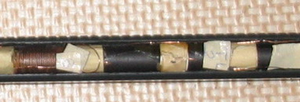
2. The entire inside of the handle is not hollow - it is filled with about a dozen transverse stiffiner ribs. Cut them all out. I used a pair of diagonal cutters and needle nose pliers. Cut the little buggers as close to the sides as possible. Stick a small steel burr or similar grinding bit into your Dremel (hobby-hand grinder) and grind the remaining rib pieces smooth to the sides of the handle. ALL THIS SOUNDS LIKE A LOT OF WORK, BUT IT REALLY ISN'T. I DID THE WHOLE PROCESS IN 30 MINUTES. Just work at your own pace and don't grind through the handle's wall. Don't do this part of the job because you have to do it - do it because you want to do it. Don't hurry - enjoy the experience - it's the best gift you can give your technical ego (satisfaction).
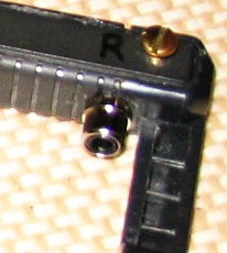
3. BEFORE you cut the wires from the radio to the antenna rod, MARK THEM! There are 6 wires,but you only need to worry about 4 of them. Two are for the oscillator winding and 2 are for the tuning section. Looking at the PC board, right side up, you can identify the wires as: left-top, left-bottom, right-top, right-bottom -- easy, huh? I wrote the letters "LT, LB, RT, RB on small strips of masking tape (see closeup below), and attached the tape to the antenna wires VERY CLOSE to the rod ... not toward the radio end! The last 2 wires go to the external antenna winding and really don't need any markings since they are so obvious. Now, go ahead and unsolder or cut the wires free from the radio.
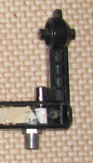
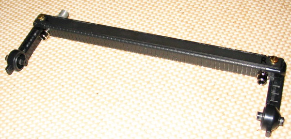
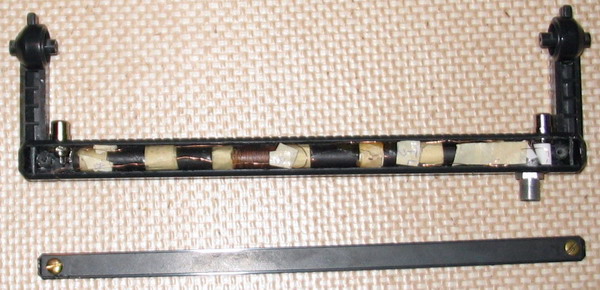
4. GENTLY place the rod into the hollowed out handle. Note how much room you have at each end -- not too much. Center it so that the space on each end is equal and check with your choice of connector to be sure it will fit. I elected to use chassis mount RCA phono connectors, but you decide what you want to do. I don't recommend hard wiring to the thin wires - they are just fragile and really need some strain relief. I drilled two 5/16" holes (.312") dead center on the first rib at each end (see photo). This is about the only way it's going to work.
5. The external antenna connection is very important for this radio, and I decided there is only one way to fit a decent RF connector for my version. At the end of the rod where the external coils is, I drilled a 3/8" (.375") hole VERY CLOSE to to RCA socket, but on the opposite side. If you make careful measurements, you'll see that it's all quite doable.