Chapter 10 :
Structured System Requirements: Conceptual Data Modeling


Objectives
- Concisely define each of the following key data-modeling terms: entity type,
attribute, multivalued attribute, relationship, degree, cardinality, business rule,
associative entity, and trigger.
- Draw an entity-relationship (E-R) diagram to represent common business situations.
- Explain the role of conceptual data modeling in the overall analysis and design
of an information system.
- Distinguish between unary, binary, and ternary relationships, and give an example of each.
- Define four basic types of business rules in an E-R diagram.
- Explain the role of CASE technology in the analysis and documentation of data required in an information system.
- Relate data modeling to process and logic modeling as different views of describing an information system.
Chapter Overview
 The purpose of this chapter is to present a detailed description of the techniques used to structure the data
requirements for an information system application. The chapter emphasizes entity-relationship (E-R) diagramming, the
most common notation used by practicing systems and data analysts. The chapter explains how E-R diagramming is used
along with process and logic modeling techniques to develop a thorough, unambiguous description of system requirements.
In addition to the standard constructs of the E-R model (entities, attributes, and relationships), we also describe the
data-oriented questions that should be raised during requirements determination so that an analyst can do data modeling.
The chapter also introduces the modeling of business rules for entity integrity, referential integrity, domains, and
triggering operations using both E-R diagrams and textual constraint statements.
The purpose of this chapter is to present a detailed description of the techniques used to structure the data
requirements for an information system application. The chapter emphasizes entity-relationship (E-R) diagramming, the
most common notation used by practicing systems and data analysts. The chapter explains how E-R diagramming is used
along with process and logic modeling techniques to develop a thorough, unambiguous description of system requirements.
In addition to the standard constructs of the E-R model (entities, attributes, and relationships), we also describe the
data-oriented questions that should be raised during requirements determination so that an analyst can do data modeling.
The chapter also introduces the modeling of business rules for entity integrity, referential integrity, domains, and
triggering operations using both E-R diagrams and textual constraint statements.
- Introduction.
- Conceptual Data Modeling.
- Gathering Information for Conceptual Data Modeling.
- Introduction to E-R Modeling.
- Conceptual Data Modeling and E-R Modeling.
- Business Rules.
- The Role of CASE in Conceptual Data Modeling.
- An Example of Conceptual Data Modeling at Hoosier Burger.

 Introduction.
Analysis is divided into :
- Requirements Determination
- Requirements Structuring.
- Process Modeling. (Chapter 8)
- Logic modeling. (Chapter 9)
- Conceptual Data Modeling. (Chapter 10)
- Alternative Generation & Selection. (Chapter 11)
DFD and various processing logic techniques show how, where, and when data are used or changed in an information system,
but these techniques do not show the definition, structure, and relationships within the data. Data modeling develops
this missing, and crucial, peice of the description of an information system.
Why data model is the most important part of the statement of the information system requirements:
- The characteristics of data captured during data modeling are crucial in the design of databases, programs, computer
screens, and printed report.
- Data rather than processes are the most complex aspects of many modern information systems and hence require a
central role in structuring system requirements.
- Characteristics about data (length, format, and relationships with other data)) are reasonably permanent.-data
flow are dynamic.
The most common format used for data modeling is entity-relationship (E-R) diagramming.
Return
Conceptual Data Modeling:
A detailed model that captures the overall structure of organizational data while being independent of any database
management system or other implementation cosiderations.
You typically do conceptual data modeling in parallel with other requirements analysis and structuring steps during
systems analysis.
Relationship between data modeling and SDLC
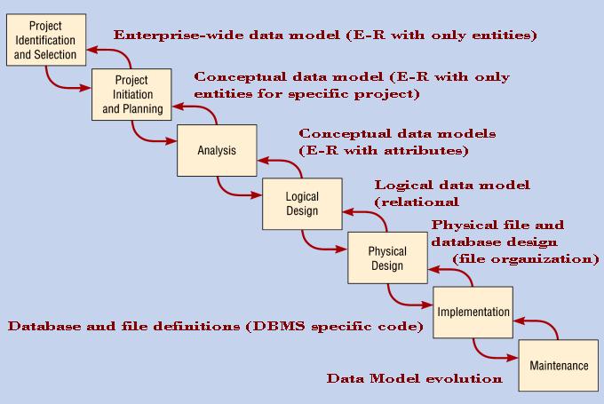
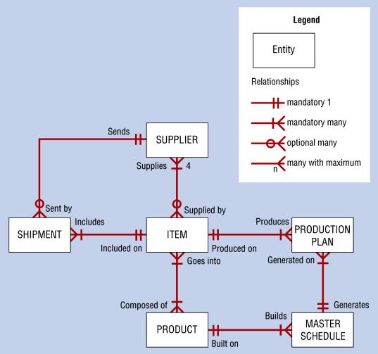
Figure 10-3
Sample Conceptual Data Model Diagram
Return
Gathering Information for Conceptual Data Modeling:
Requirements determination methods must include questions and investigations that take a data, not only a process and
logic, focus.
Top-down approach. other methods of data gathering from documents, computer displays, reports, and business forms.
See fig 10-4 and Table 10-1 for more details.
Return
Introduction to E-R Modeling:
The basic entity-relationship modeling notation (Chen, 1976) uses three main constructs: data entitie, relationships,
and their associated attributes.
Entity-relationship data model (E-R model):
A detailed, logical representation of the entities, associations, and data elements for an organization or business area.
Entity-relationship diagram (E-R diagram):
A graphical representation of an E-R model.
Entity:
An entity is a person, place, object, event, or concept in user environment about which the organization wishes to
maintain data. An entity has its own identity which distinguishes it from each other entity.
Entity instance:
A single occurence of an entity type
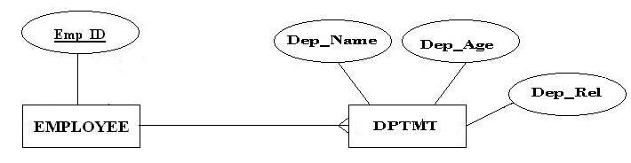
See figure 10-5 page 352 Entity-relationship notation.
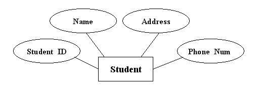
Attribute:
A named property or characteristic of an entity that is of interest to the organization.
Student: Student_ID, Student_Name, Address, Phone_Number, ...
Automobile: Vehicle_ID, Color, Brand, Weight, Horsepower, Fuel_Consumption,...
Cadidate Key:
An attribute (or combination of attributes) that uniquely identifies each instance of an entity type.
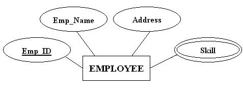
Identifier:
A candidate key that has been selected as the unique, identifying characteristic for an entity type.
Multivalued Attribute:
An attribute that may take on more thanone value for each entity instance.
Repeating group:
A set of two or more multivalued attributes that are logically related
Relationship:
An association between the instances of one or more entirty types that is of interest to the organization.
Return
Conceptual Data Modeling and E-R Modeling:
Degree:
The number of entity-types that participate in a repationship
Figure 10-6
Example Relationships of Different Degrees
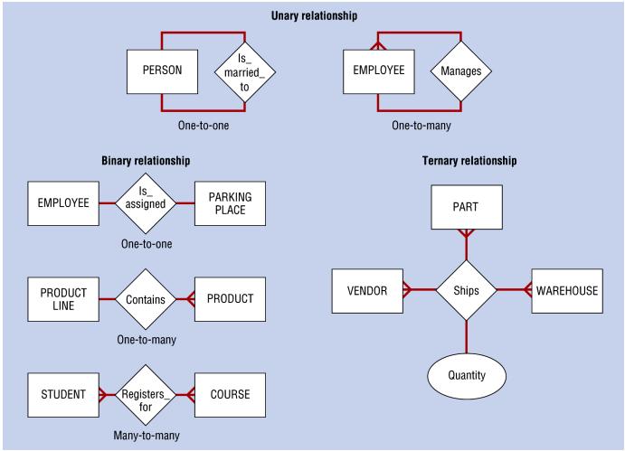
Figure 10-7
Bill of Materials Unary Relationship
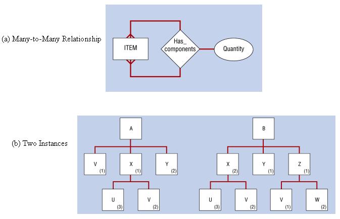
Unary relationship (recursive relationship):
A relationship between the instances of one entity type.
Binary relationship
A relationship between the instances of two entity types. Tis is the most common type of relationship
encountered in data modeling
Ternary relationship:
A simultaneous relationship among instances of three entity type.
Cardinalities in Relationships:
Cardinality is the number of instances of an entity that can (or must) be associated with each instance of another entity.
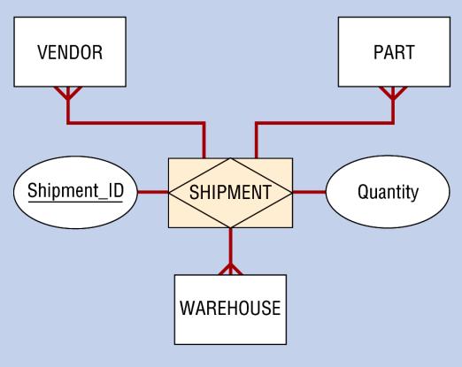
Associative Entities:
See figure 10-8 page 360
Associative entity:
An entity type that associates the instances of one or more entity types and contains attributeas that are peculiar
to th relationship between those entity instances; also called a gerund.
Figure 10-9
Example Associative Entity
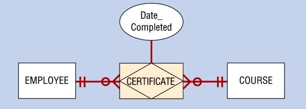
Figure 10-10
SHIPMENT Entity Type (an Associative Entity)
Return
Business Rules:
Business rules:
Specifications that preserve the integrity of conceptual or logical data model.
Domain:
The set of all data types and values that an attribute can assume
Figure 10-11
Examples of Business Rules

Triggering operation (trigger):
An assertion or rule that governs the validity of data manipulation operations such as an insert, update, and delete.
Return
The Role of CASE in Conceptual Data Modeling:
Case tools provide two important functions in conceptual data modeling:
- Maintaining E-R diagrams as a visual depiction of structured data requirements, and
- Linking objects on E-R diagrams to corresponding descriptions in a repository.
Fig 10-12 page 367 lists the typical dat model elements that are placed in the project dictionary or CASE repository
conceptual data modeling.
Return
An Example of Conceptual Data Modeling at Hoosier Burger:
Figure 10-13
Level-0 data flow diagram for Hoosier Burgur's new logical inventory control system

Figure 10-14 page 368 shows the reduced decision table for Hoosier Burger's inventory reordering.
Figure 10-15
Preliminary E-R Diagram for Hoosier Burger�s Inventory Control System

Figure 10-16
Final E-R Diagram for Hoosier Burger�s Inventory Control System
