
Rotating Magnet
Physics
World
Back to Electrodynamics
In the following page we
find the both the volume and surface charge distribution on a cylindrically
symmetric rotating magnet such as that shown in Figure 1 below

To solve this problem
we'll model the magnet as a collection of magnetic dipoles where each dipole
will be modeled as a loop of current. In order to obtain an intuitive feel for
the physics one can break the problem down into separate pieces for analysis and
work to the desired solution.
Charged Density on a Moving Wire
We therefore start with a
long straight current carrying wire that has a charge density, r,
which is zero in the “rest frame” S (the inertial frame in which the wire is
not moving), herein after referred to as frame S’. We then find the charge
density in a frame, S’, moving with respect to the S. [1]
First
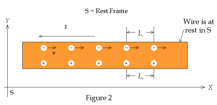
consider the charge densities in S, the rest frame of the wire. The wire is at
rest lying parallel to the x-axis as shown below in Figure 2
The current is flowing in
the -x direction as shown in Figure 2, which means that electrons are
flowing in the +x direction. Since the wire is electrically neutral (i.e.
r
= 0) in S it follows that both the positive and negative charge densities are
equal, i.e.,
![]()
Since the magnitude of the
charge of a proton is equal to the magnitude of the charge of an electron then
we can assume, for the sake of simplicity, that the "+" charges are
equally spaced a distance L = L+
apart and all the "-" charges are equally spaced a distance L =
L- apart as well. We can look
at the “+" charges as defining the rest frame S. It then follows that the
"+" charges are at rest in frame S and that the "-"
charges are moving in the +x direction, with speed v (drift
velocity) as measured in S. See Figure 3 below
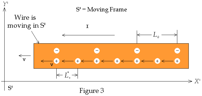
We now transform to the
frame, S', in which the “-“ charges are at rest. This is the frame moving in
the +x direction with speed v. The “+” charges are now are
moving in the -x direction with speed v. In S' the distance
between the "+" charges will be decreased due to a Lorentz contraction
by the amount
![]()
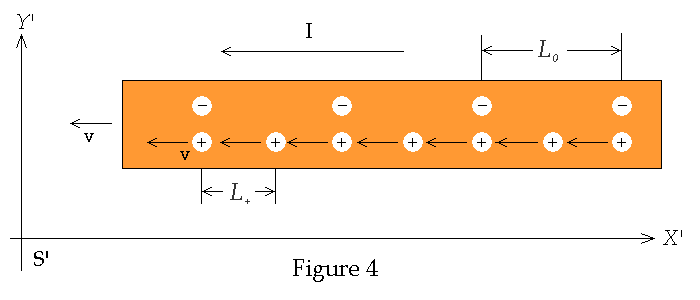
As measured in S the
distance between the charges was Lorentz contracted from its proper length L0.
The distance between the charges in frame S’ is now larger since there is no
Lorentz contraction as there was in frame S. The two distances L-
and L0 are related by the
expression
![]()
These densities are
illustrated Figure 4 below
Since charge is invariant
it follows that charge densities transform as
![]()
where r0
is proper charge density, i.e. the density of charge as measured in the frame in
which the charges are at rest (Note: this only applies when there
is a frame of reference where all charges are at rest – otherwise charge
densities have to be added as in the present case). Therefore the following
relations hold true


The charge density in S’
can now be found by substituting Eq. (6) into r’
= r’+
+ r’- and
noting From Eq. (1) that r’-
= - r’+

![]()
It is therefore seen that
there is a non-zero volume charge density along the wire in the S’
frame but not in the rest frame S. These calculations can be found in the Feynman
Lectures- V-II [1] and in A.P. French’s Special Relativity [2]
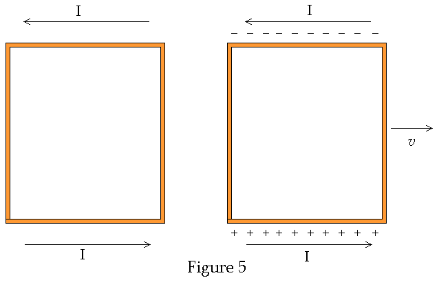
Some reflection on the
above arguments will show that no change in charge densities will occur if the
wire is moving perpendicular to it's length as seen in Figure 5 below
With the above arguments we can now analyze the current loop
as shown in Figure 6 below
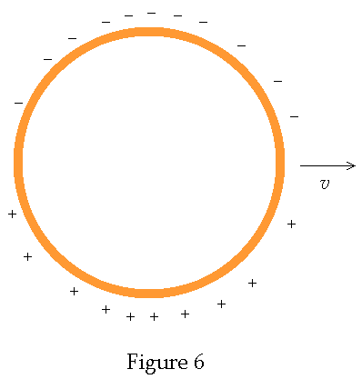
Thus when the current loop
is at rest it's uncharged. When it's moving it becomes charged as shown. Note
that a current loop is magnetic dipole. Therefore a magnetic dipole at rest
becomes magnetic dipole which has is similar to an electric dipole when moving!
For a circular loop the charge density will be greatest on the top and bottom
and it will decrease along the wire until it reaches zero at the left and right
most points on the wire as indicated in Figure 7 below
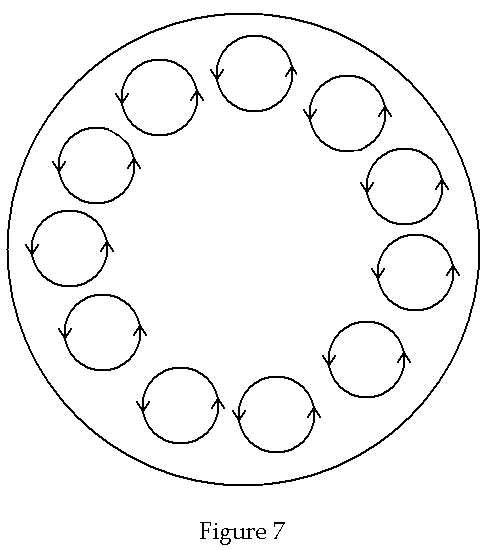
Now returning back to the
rotating magnet we consider the magnet as consisting of current loops as shown
in Figure 8 below
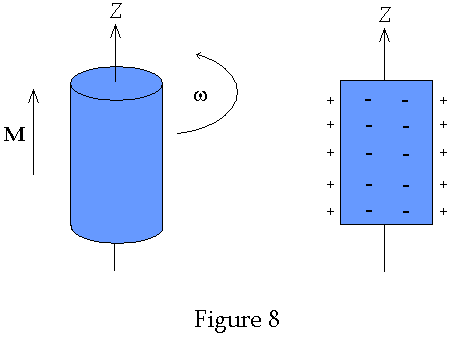
As the entire assembly
rotates the individual loops become charged according to the velocity of that
portion of the wire. Notice that portions of the loop closer to the center move
slower and therefore become less charged. The net effect is that there is a net
surface charge density and net volume charge density. The exact values are
calculated next.
Consider a cylindrical
magnet with uniform magnetization that is rotating about its axis of symmetry.
Let the axis of rotation be the z-axis as shown in Figure 1 above.
A magnetic dipole
density, M, and an electric dipole density, P, characterize the
non-rotating magnet. In this problem it is assumed that the magnet is uncharged
when not rotating, i.e. the total charge is zero, and therefore P
= 0 on the entire surface. According to the law of conservation of charge the
total charge on the magnet must remain zero at all times. Our aim is to find M'
and P' when the magnet is rotating. It can be shown using
Einstein's special theory of relativity; a pure magnetization M in one
frame is a combination of P and M in another frame. This
holds true even when the material is moving such that all parts have v
<< c (The dipoles are treated as moving un-accelerated in the
direction tangent to its path. It is assumed that the dipole moments, M'
and P', are not function functions of the dipole’s
acceleration).
Such is true with any
cylindrically symmetric rotating magnet. An electric field is generated from
this polarization since the polarization gives rise to volume and surface charge
densities. The volume and surface charge densities are given respectively by
[3]
![]()
n
is a unit vector which is normal to the surface. The parallel and perpendicular
components of P' are [4]

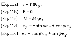
Note: “r” is
the perpendicular distance from the point of interest to the z-axis. M0
= constant inside magnet, vanishes outside. All parts of magnet moving at v
<< c Ž g
= [1 – (v/c)2]–1/2 << 1.

![]()
To find the volume and
surface charge densities we employ Eq. (8a) above.

On the side surface of the
magnet r = R and n = er.
The only non-vanishing contribution comes from the side surface. Therefore set r
= R and n = er
and use Eq. (8b) above to get

Total volume charge: QV
Total surface charge: QS
Total charge: QT = QV + QS
![]()
![]()
![]()
This is a satisfactory
result since we assumed that the total charge, i.e. surface charge on the
magnets surface and volume charge with the volume of the magnet, must remain
zero per the law of conservation of charge.
These charge distributions are shown in the Figure 8 below. The figure on
the left just shows the rotating magnet while the figure on the right just shows
the surface and volume charges
Applications in
Astrophysics - Neutron Star
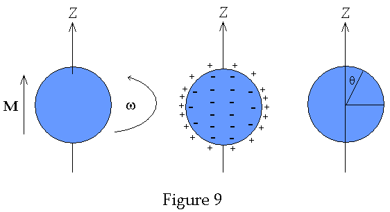
Suppose we used a sphere instead of the cylinder. Then the r will still be constant but s will vary as sin2 q where w is the angle measured from the z-axis as shown in the diagram below, i.e. Figure 9. Therefore s will be maximum where q = p/2 vanish where q = 0 and p etc. The magnetic fields generated by Neutron stars are extremely strong. Assuming a uniform magnetization it is thus seen that a rotating neutron star will have a charge density as shown Figure 9 below
References:
[1] The
Feynman Lectures on Physics - Volume
II, Feynman, Leighton and Sands, Addison Wesley, 1977, pages
13-7 to 13-12.
[2] Special Relativity, A.P. French, W.W. Norton and Co. (1968),
page 259.
[3] Classical Electrodynamics – Second Ed., Hans C. Ohanian, Infinity
Science Press, (2007), page 118.
[4] Classical Electromagnetic Theory, Jack Vanderlinde, John Wiley
& Sons, Inc., (1993), page 306.