| By Dan Moore |
e-mail |
Return to my
Dark Eldar Home Page |
The following is a procedure for modifying the Dark Eldar raider transport model to give it a removable tail section. I developed this modification to the model so that it can be packed and transported more easily. On several occasions in the past I had problems with breakage of the tail during transport because the model is large, bulky, and has numerous projections that catch on things. The same removable tail modification can be adapted for Dark Eldar Ravager models or any custom model that uses the Raider transport(Asdrubael Vect for instance.)
Sharp razor knife (Xacto or similar), Razor saw or jewelers saw, Jewelers Files
Rotary tool (Dremel) with abrasive cutting wheel, Polystyrene glue, 5-minute epoxy
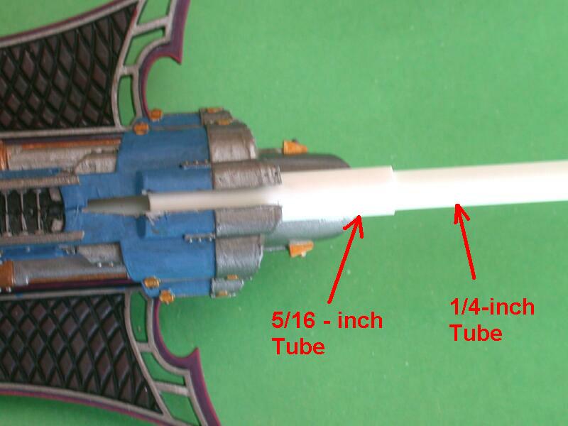
1/4-inch (6.4 mm) polystyrene tube with 4+ inch length (I use tube from Evergreen Plastics)
5/16-inch (7.9 mm) polystyrene tube with 3+ inch length, it must slide over 1/4-inch tube (I use tube from Evergreen Plastics)
1/16-inch (1.6 mm) polystyrene sheet (2 inch x 1 inch piece), Raider model – assembled or disassembled
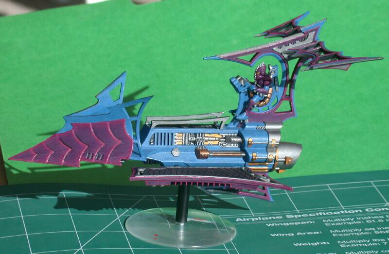 This is a the raider that will be converted |
 Use a sharp hobby knife, preferably with a new blade |
 A rotary cutting tool will be useful for cutting slots in the model. |
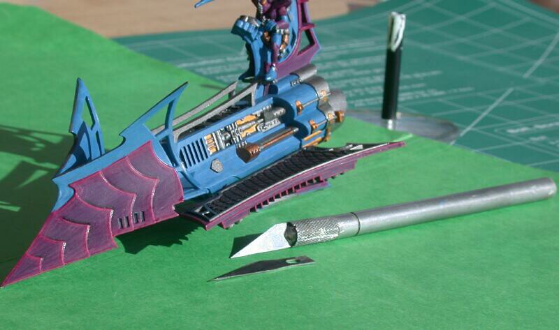
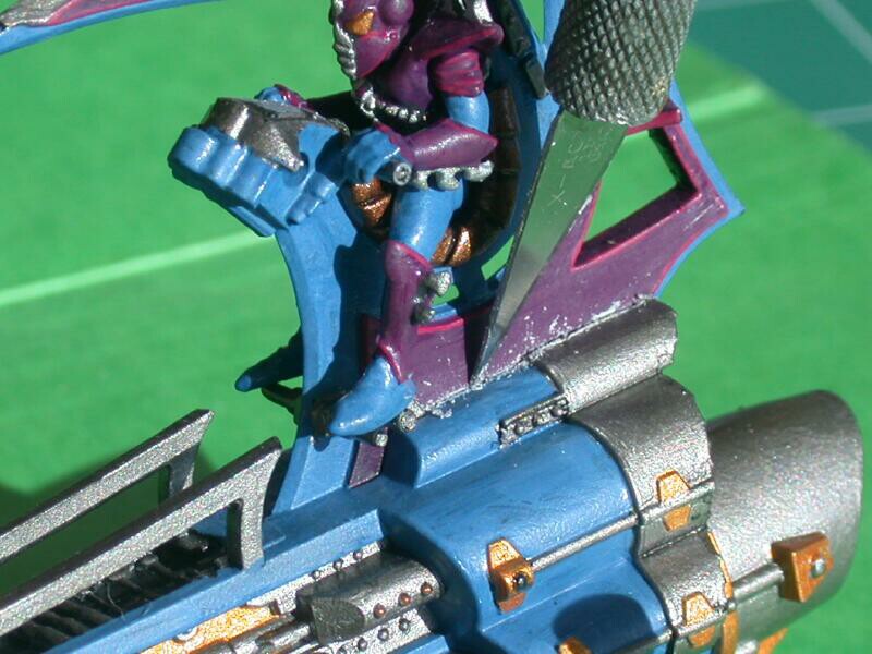
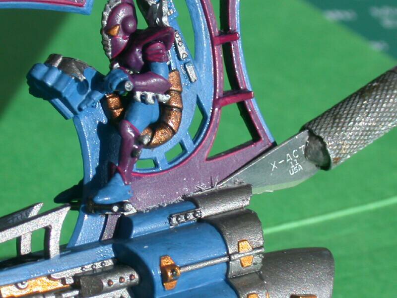
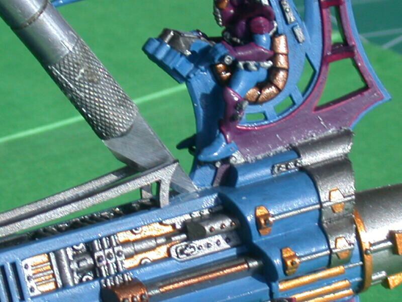
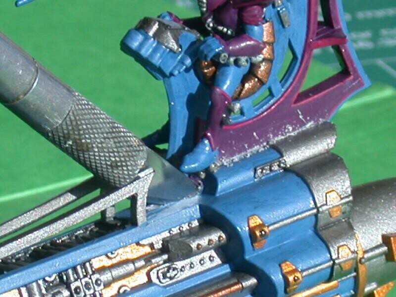
Use a knife or saw to do this. There are two ways to cut away the tail: you can cut it off flush with the main raider body or preferably cut into the body and remove the tail and small section of the body attached to the tail. The latter is more difficult with an assembled model. You will need a sharp knife, and you will need to make progressively deeper scores/cuts in the plastic until you cut through. Normally, you will only need to cut the plastic on the left side of the raider tail because the right side forms part of the joint between the two raider halves. If you happened to glue the raider together at the tail section then you will need to cut away the tail section on both sides. The illustrations below show the method for removing the raider tail by cutting into the body of the model. This is more challenging but it removes the tail and leaves a needed slot in the raider body.
|
|||
|
|||
|
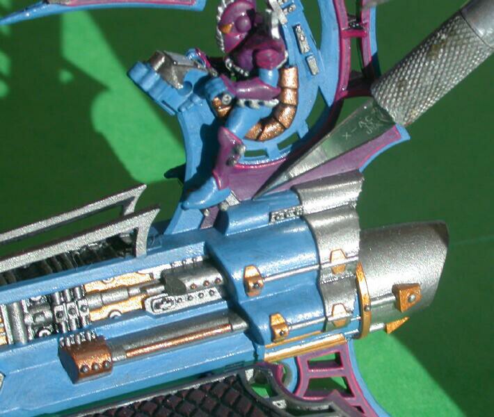
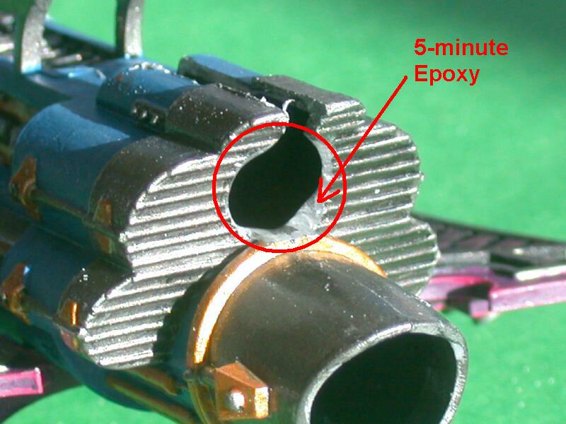
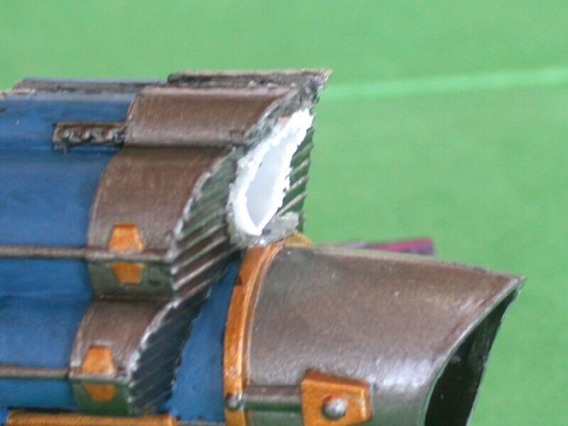
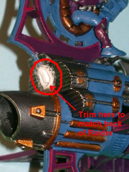
This hole will be where the tail section slides into the model for final assembly. The hole is located where circular disk is above the raider’s jet exhaust port. The disk is approximately 5/16-inch diameter and has several raised ridges on it. Carefully cut around the disk with a hobby knife and remove it. Save the disk, as you will need it later. If necessary, enlarge the hole slightly until the 5/16-inch polystyrene tube fits snugly in the hole.
 Use a sharp hobby knife to score and cut around the perimeter of the ribbed disk above the jet nozzle of the raider. |
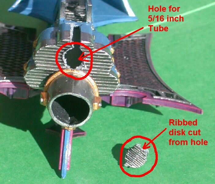 A rear view of the raider
showing the removed ribbed
disk and the circular hole where
the disk was located. A rear view of the raider
showing the removed ribbed
disk and the circular hole where
the disk was located. |
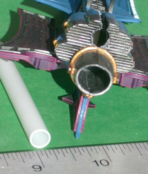 5/16-inch diameter polystyrene tube will be insterted into the hole in the back of the raider. |
The tube will ultimately be inserted into the hole that you cut in step 2 and then it will be bonded to the raider body with polystyrene cement and/or epoxy. First however, the 5/16-inch tube will need to have a "step" or notch cut in one end to match the raider body. The "step" or notch helps to locate the tube in the raider and provides more surface area to insure a good bond between them. The notch will be approximately 3/8-inch long and cut through roughly half of the diameter of the tube. The slot can be cut with a knife or rotary tool.
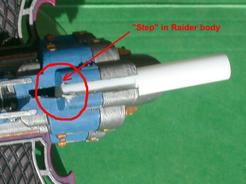 The 5/16-inch tube is inserted until it contacts the "step" in the raider body. |
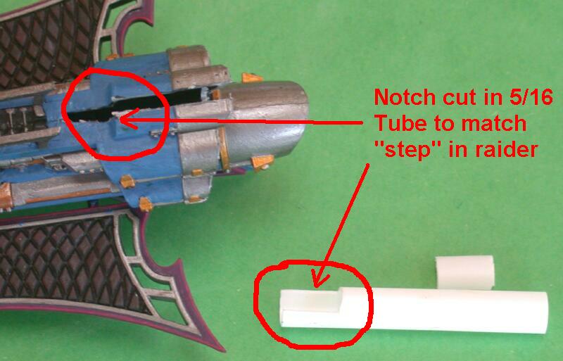 A "step" or notch is cut in the 5/16-inch tube to match the raider body. |
 The modified 5/16-inch tube is inserted into the raider and checked for fit. |
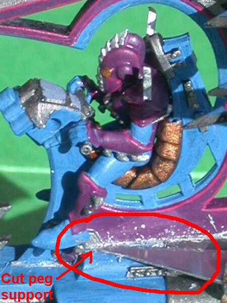
This extension will be made by gluing the 1/16-inch polystyrene sheet to the cut portion of the tail section. The sheet should extend the bottom edge of the tail section at least 1/4-inch. Later, in step 9, the tail section extension will be trimmed to fit in the slot in the raider body. I prefer to make a cutout in the bottom of the tail section that matches a tab that I make in the polystyrene sheet. The tab fits into the cutout and helps to lock the two pieces together. You can use polystyrene glue to bond the pieces. I also use 5-minute epoxy to fill any gaps.
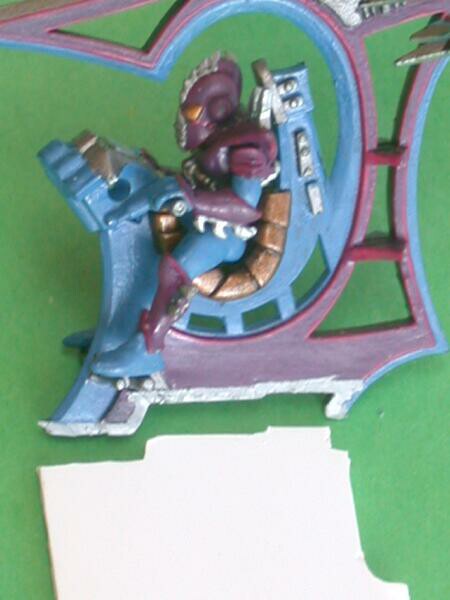 A 1-inch x 2-inch piece of 0.062-inch thick polystryrene sheet is cut to match the bottom edge of the raider tail section. |
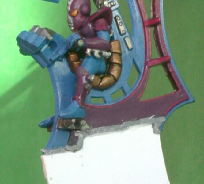 The 0.062-inch sheet is bonded to the tail section with polystyrene glue. Epoxy can be used to fill any gaps between the pieces. |
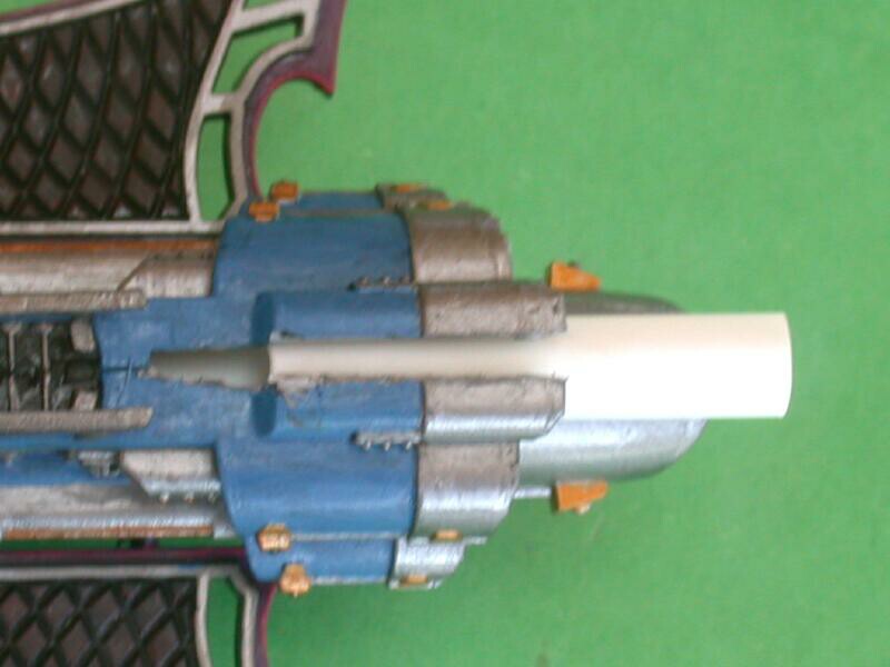
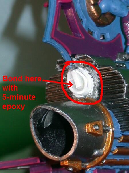
The 5/16-inch tube can now be mounted and glued into the raider body. I like to use both polystyrene cement and 5-minute epoxy to glue the tube in place. The polystyrene cement is applied to the end of the tube with the “step” slot. Inside the hole (from step 2) in the back of the raider I will apply a generous bead of 5-minute epoxy. The end of the tube with the “step” will be inserted into the raider body first and pushed until it contacts the “step” in the raider body. Approximately 1-inch of the 5/16-inch tubing will be inserted into the raider body. The remaining tubing will protrude from the back of the raider model. You can move this protruding tube to adjust the angle and position to insure that that it is located properly. When doing this adjustment it is helpful to insert a long length of 1/4-inch diameter tube to assist with moving and aligning the 5/16-inch tube. The long axis of the tube should run parallel to the top of the raider body. While the glue is drying/curing, position the raider body vertically with the front pointing up. The tube(s) will point downward and the epoxy bead at the hole will flow down into any gaps between the tube and the back of the raider.
|
|||
|
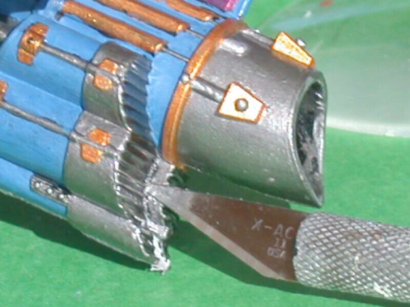
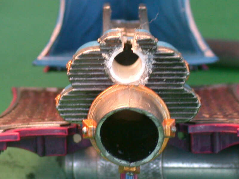
The extra tubing that protrudes from the back of the raider can be cut away with a razor knife. Use a file to clean the edges and blend them with the back of the raider body. Inspect the interior of the 5/16-inch tube. It should be free of any excess glue. If necessary clean out the tube with a file or rotary tool.
This slot is approximately 1/8-inch wide and is located where the tail section was cut away. If the tail was flush cut, then you will need to make a slot. If the tail and part of the body were cut away then there will already be a slot and it will only need to be enlarged slightly. You can use a razor saw and file to cut/form the slot or a rotary tool with abrasive cutting wheel (preferred.) The slot should begin at the front edge of the tail section and proceed back through the rear wall of the model. It will intersect the hole that you cut in Step 2. You only need to cut the slot deep enough to pass through the wall thickness of the plastic tube, no more than 1/8-inch deep.
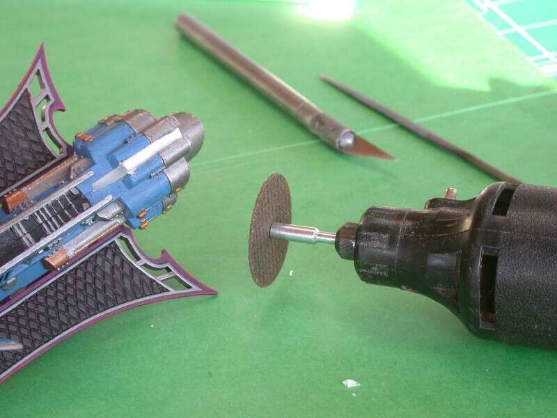
| A rotary tool with an abrasive cutting disk can be used to cut the slot in the 5/16-inch tube and enlarge the slot in the raider body. |
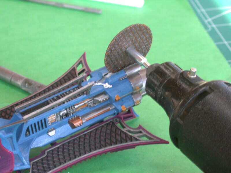 A view of the rotary tool making the slot.. The slot will need to be approximately 1/8-inch wide. |
 A top veiw of the raider where the slot was just cut. There are gaps between the raider body and 5/16-inch tube. |
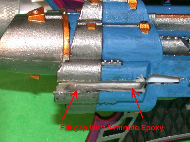 The gaps can be filled with 5-minute epoxy to to reinforce the bond between the tube and the raider model. |
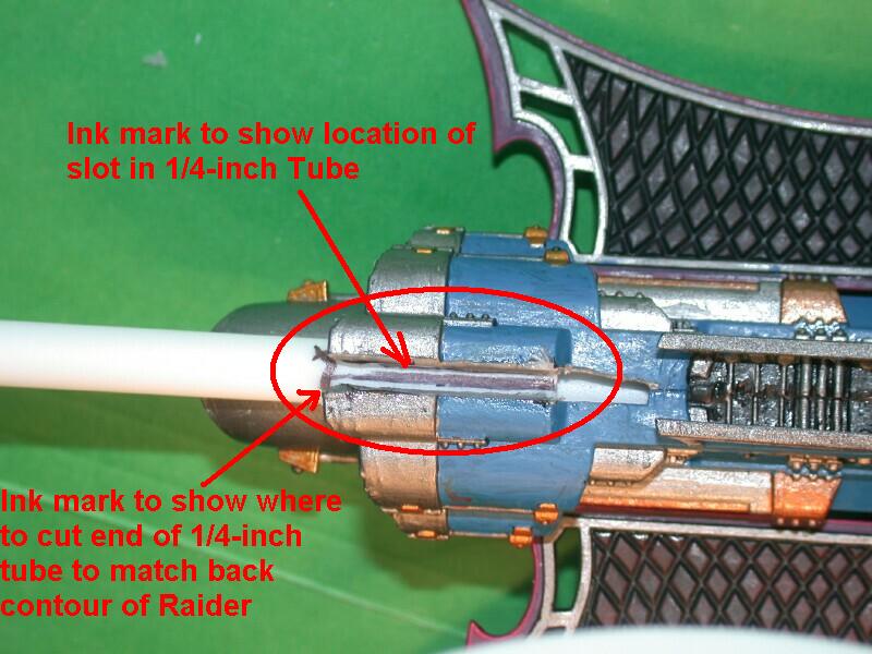
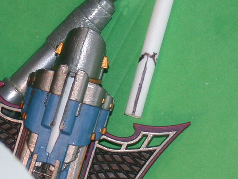
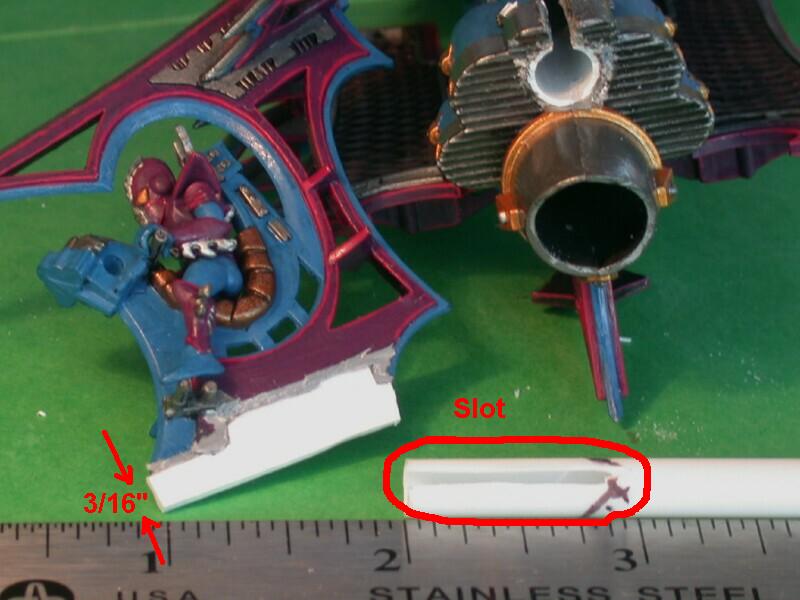
This slot should be approximately 1/16-inch wide and 1-inch long. The slot should be wide enough to snugly hold the raider tail extension that was added in step 4. The 1/4-inch tube can be inserted into the 5/16-tube in the raider body and marked with a pen to determine the position and length of the slot. The slot can be cut with a razor knife or rotary tool. The 1/4-tube can also be marked along the rear edge of the raider body. This marking can be used later when the 1/4-inch tube is trimmed to match the rear contour of the raider.
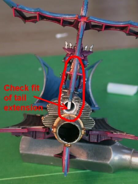
In step 4 a piece of 0.062-inch thick polystyrene sheet was glued to the tail section to extend it. This sheet will be needed to be trimmed to the correct length so that it fits into the slot and 5/16-tube that was added to the raider. Approximately a 1/4-inch length of sheet should protrude from the bottom edge of the tail section. The tail section can be positioned in the slot and checked for fit to determine how much polystyrene sheet needs to be removed.
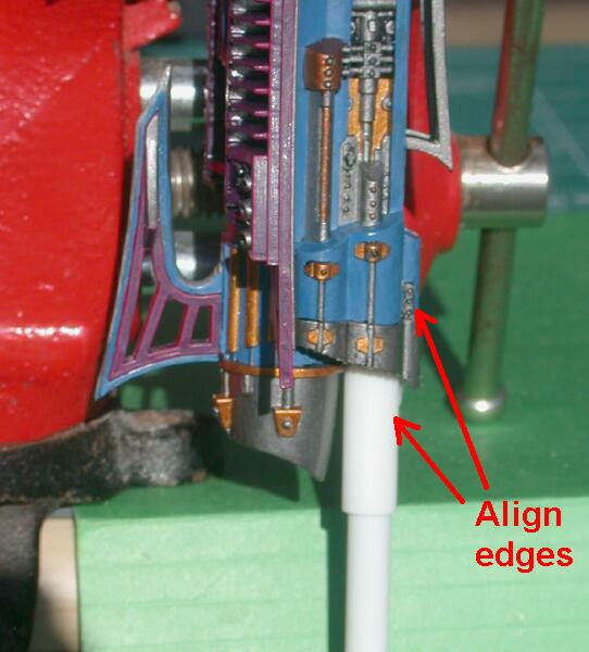
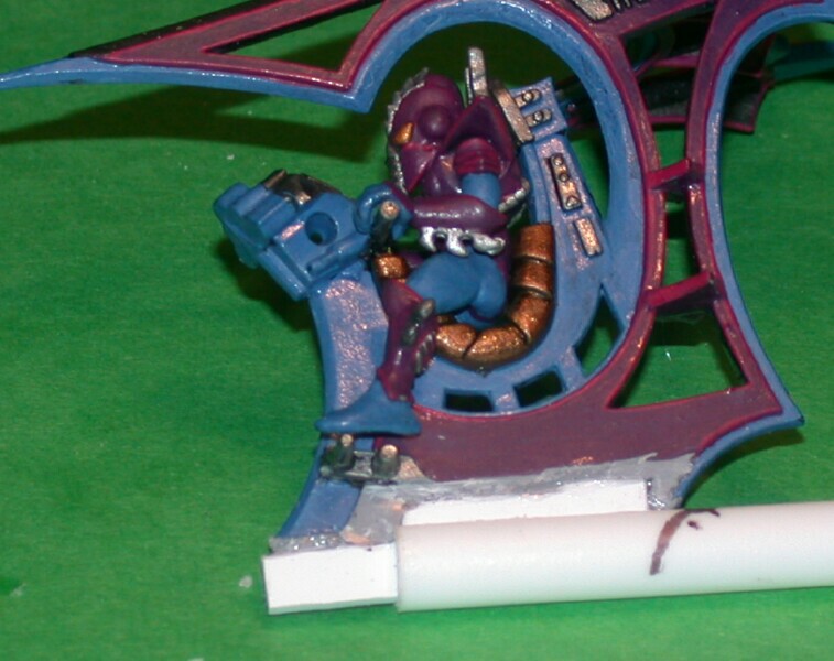
The 1/4-inch tube should be placed into the 5/16-inch tube that was glued into the raider body. The slot in the tubing should align with the slot in the 5/16-inch tube and raider body. The tail section and extension should then be placed in the aligned slots so that it is in the same position as it was in the original model. The tail section should project vertically from the raider body and the back edge of the tail section should match the back edge of the raider body. Once this is completed you will notice that part of the tail section extension protrudes into the 1/4-inch tube. A small amount of polystyrene cement should be applied to the joint between the 1/4-inch tube and tail section extension. Allow the glue to cure and then carefully slide the tail section and attached 1/4-inch tube out of the back of the raider body.
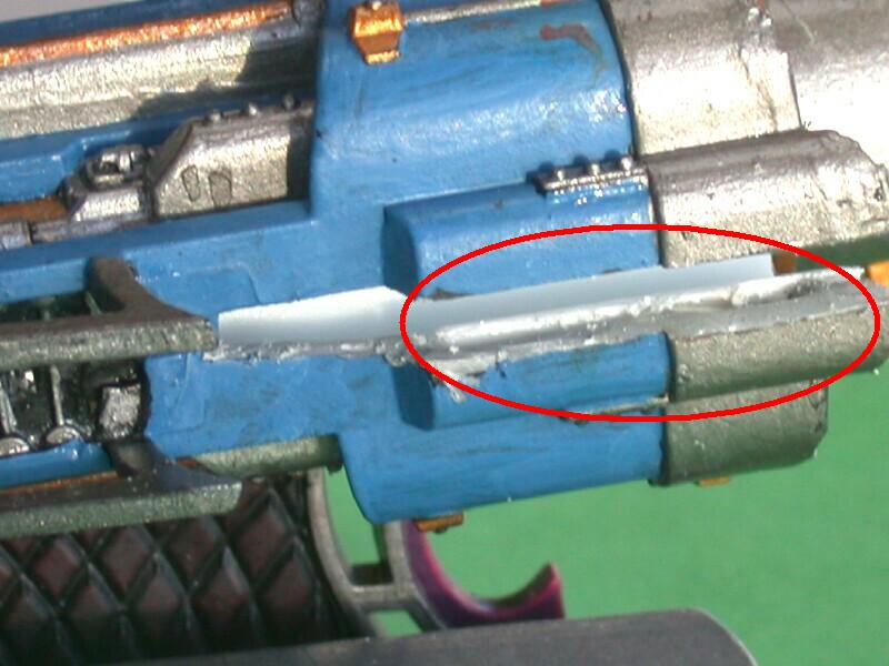
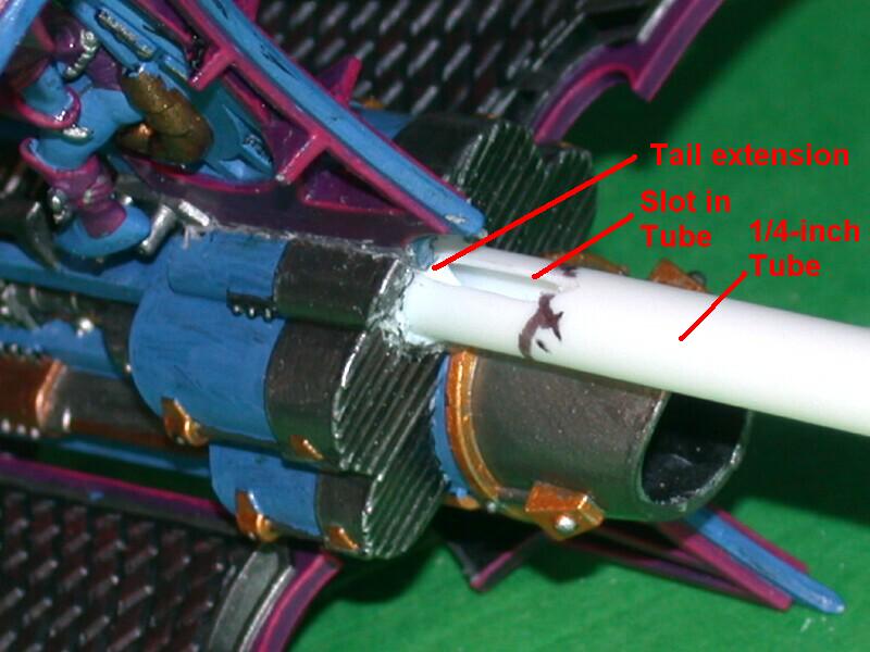 The tail section is inserted into the slot in the raider. Next the 1/4-inch tube is inserted into the 5/16-inch tube in the raider body. The slot in the 1/4-inch tube should align with the tail section |
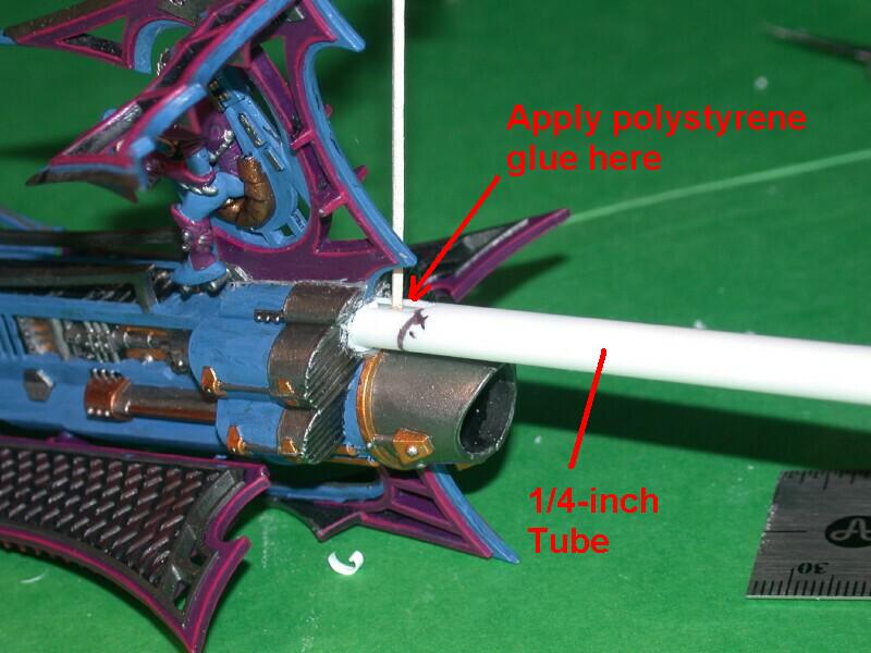 A small amount of polystyrene glue is applied to the slot in 1/4-inch tube. This will temporarily bond the tail section to the 1/4" tube. |
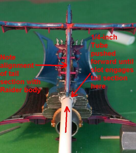 The 1/4-inch tube is pushed into the raider until the end of the slot touches the tail section. The glue is allowed to cure to tack the pieces together. |
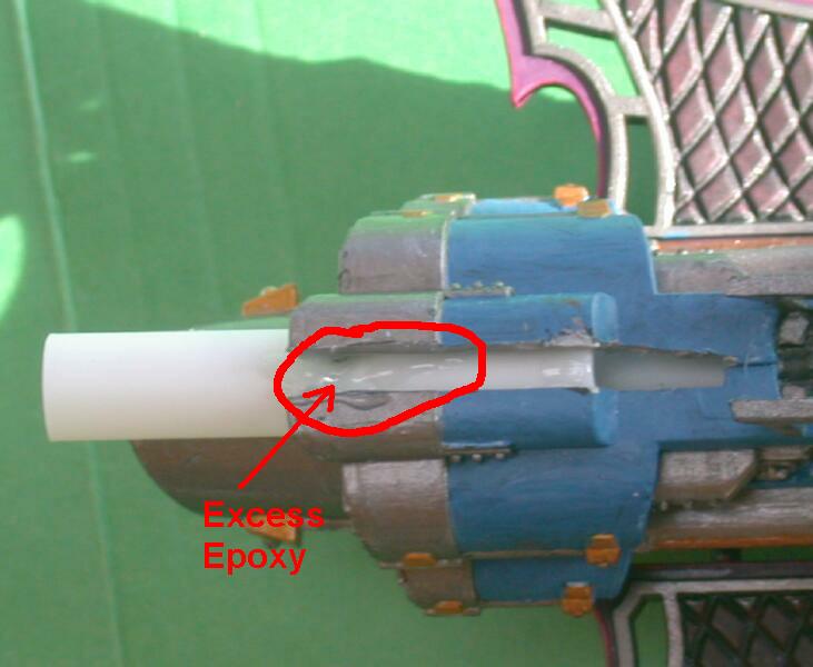
 The tail section and attached 1/4-inch tube are carefully removed by sliding them out of the back of the raider. The pieces can now be more securely bonded with epoxy. |
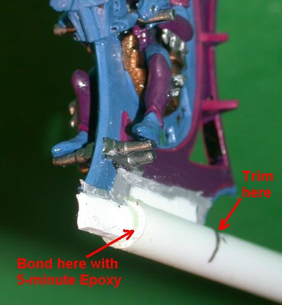 A generous amount of 5-minute epoxy is inserted into the front end of the 1/4-inch tube to securely bond it to the tail section. |
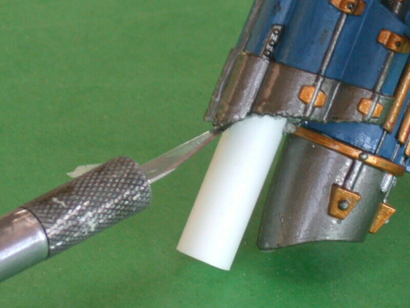
 The rear end of the 1/4-inch tube is trimmed to match the back surface of the raider. A hobby knife and file can be used to get a smoother even surface. |
 More 5-minute epoxy is used to bond the rear end of the 1/4-inch tube to the tail section. |
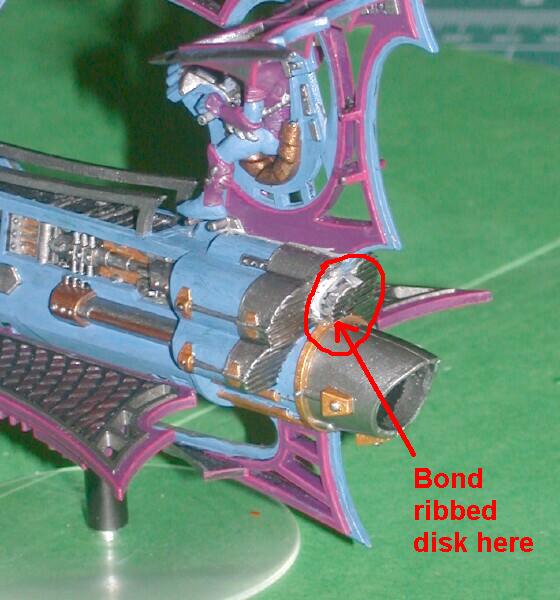 The ribbed disk that was removed in step 2 is bonded to the rear end of the 1/4-inch tube in the tail section. It should be position to match its original location. Be careful to bond it to the tail section assembly ONLY and not the raider body. |
Sand and trim the tail section, if necessary, to clean up any seams or joints. Paint as needed to match the rest of the model.
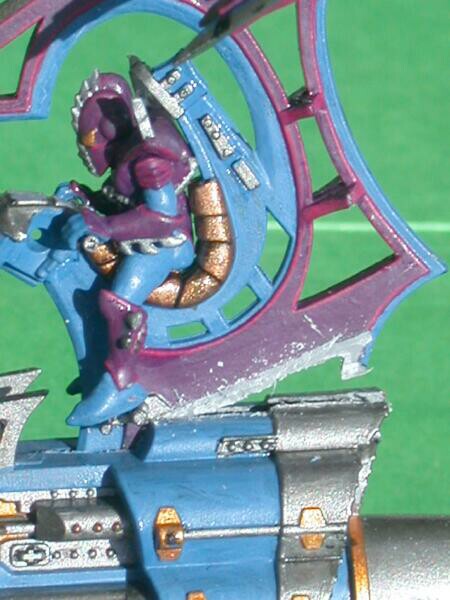
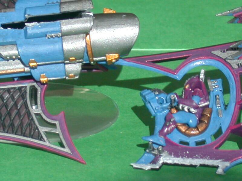
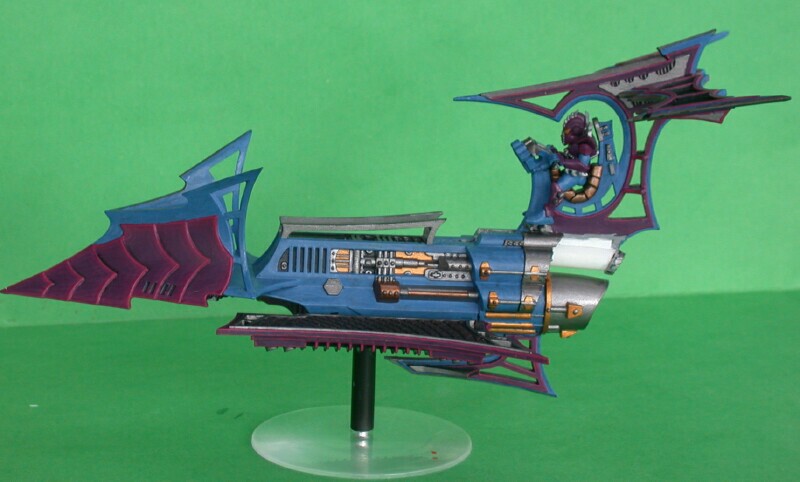
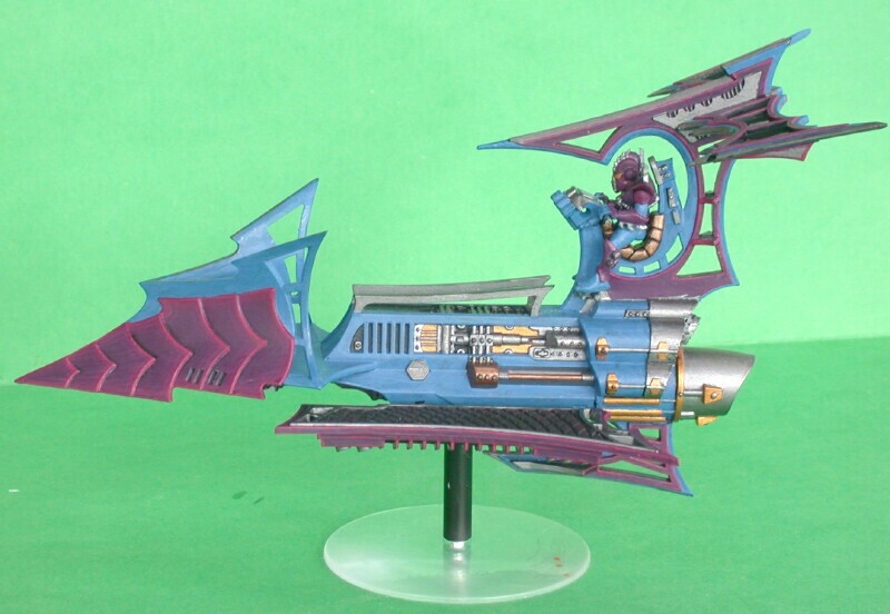 Before and after views of the raider with the tail conversion |
 A view of the raider with the tail section partially removed. |
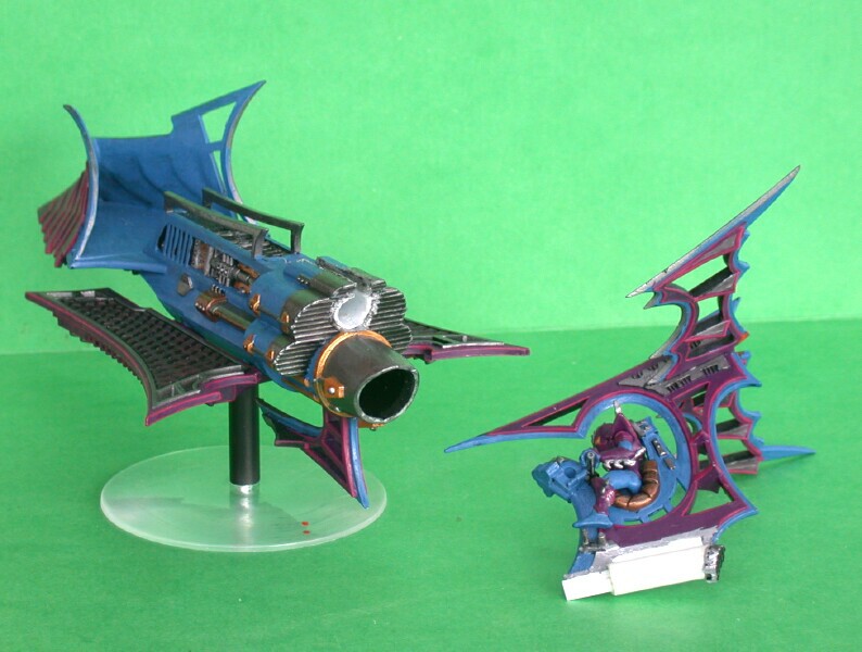 A view of the raider body and removable tail section. |