Created by Joselito Kuizon Jr.
To enter Drafting Mode, click on
the Drafting Icon ![]() or select from the Pull-Down Menu: Application > Drafting.
or select from the Pull-Down Menu: Application > Drafting.
If it is the first time the part is opened in drafting mode, a dialog box will prompt you to insert a sheet.
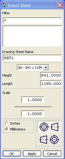
You may enter the appropriate values and click Ok.
You may edit the sheet by selecting from the Pull-Down Menu: Edit > Sheet...
2-3. Adding Views
Views are added by clicking on the
Add Base View Icon ![]() or from the Pull-Down Menu: Insert > View > Base View...
or from the Pull-Down Menu: Insert > View > Base View...
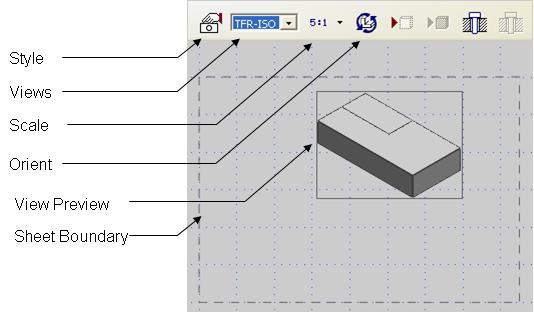
A dialog will then prompt you for the view style, view name, scale, orientation, component visibility, etc.
A preview of the view will also appear where the cursor is located.
By clicking on the Drafting graphics area, the view will be placed on that location and the next projected view is ready to be placed. A preview of the next projected view is also available.
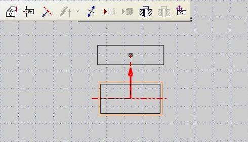
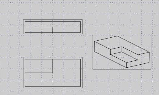
The final views are as shown.
View from other components may also
be added by clicking on the Add View from Part icon ![]() or from the Pull-Down Menu: Insert > View > Add View from Part...
or from the Pull-Down Menu: Insert > View > Add View from Part...
You are then prompted to choose the part from which the view will be displayed.
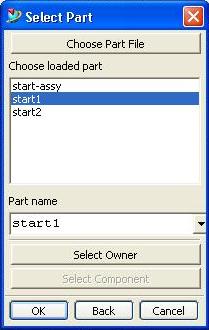
Select the part or click "Choose Part File". Click Ok.
The steps that will follow is the same as adding a Base View.
2-4. Adding Dimensions
Dimensions are added by clicking
on the Infer Dimension icon ![]() or from the Pull-Down Menu: Insert > Dimension > Inferred...
or from the Pull-Down Menu: Insert > Dimension > Inferred...
A dialog box will prompt you for the style, annotation, placement and etc.
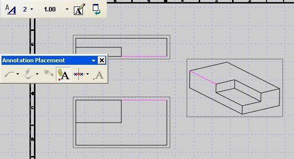
Click on the first edge or object and then click on the second edge or object you want to dimension. If you want to add a vertical dimension, click at the side of the object. If you want to add a horizontal dimension click at the bottom or top of the object.
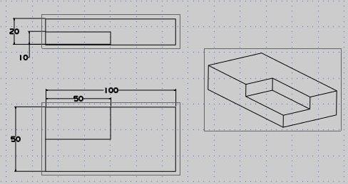
The final drawing may look something like this.