 |
|
|
|
|
|
|
|
|
|
|
|
|
|
|
|
|
|
|
|
|
|
|
|
|
|
|
|
|
|
|
|
|
|
|
|
|
|
|
|
|
|
|
|
|
|
 |
|
|
 |
|
|
|
 |
|
|
|
THE DIAGONAL MIRROR AND SPIDER |
|
|
HOME |
|
|
|
|
|
|
|
|
|
THE TUBE |
|
|
|
|
|
The purpose of the diagonal mirror flat is to reflect the image from the primary mirror up the draw tube of the focusser to the eye-piece. Ideally it would be nice if it was very small, but, its size and position in the telescope tube is determined by the diameter of the primary mirror and its focal length. A few minutes inputting various values in the Newtwin program will give a feel for the problem. Because it is fixed, you normally buy the flat along with the main mirror; they come as a pair. Mine was 1.4 inches across the smaller axis of the elipse. I needed to make a mount of that diameter with a cut at 45 deg. As usual there are plenty of designs on the Internet, take your choice. I settled for the design shown here, with a 4-vane support spider. For small telescopes like this, some advocate a single support of thicker material. |
|
|
|
|
 |
|
|
|
|
|
|
|
MIRROR CELL |
|
|
|
|
|
|
|
|
|
ASSEMBLY |
|
|
|
|
|
|
|
|
|
|
|
|
|
|
|
 |
|
|
|
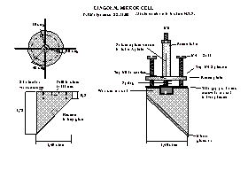
As with the main mirror, the diagonal must be able to be adjusted in all planes - and then locked into place. |
|
|
|
|
|
Let's look at the drawing: not very clear - click to open a much clearer, but bigger example. |
|
|
|
 |
|
|
CONSTRUCTION |
|
|
|
|
|
|
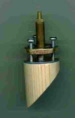
The 11/4 inch wooden dowel was cut to size at 45 deg. and a depression drilled out in the top face to provide clearance for the centre bolt, and another similar size hole drilled in the angled face to provide some extra glueing area for the silicone mirror adhesive. To provide a decent bearing surface for the three adjustment screws, I fixed a disk of thin printed circuit board to the top with two small counter-sunk woodscrews. A hole in the middle clears the bolt shank - but holds it captive by its head. This needs to be done well as it is the only fixing stopping the mirror flat falling off down onto the primary mirror !. |
|
|
|
The mounting was sawn and filed from 3/16" brass, drilled and tapped in the centre to accept the bolt. Three more holes were drilled and tapped 120 deg. apart for the adjustment bolts. Instead of tapping the holes, I could have soldered on appropriate nuts instead. Next a piece of brass tubing, with clearance for the bolt, was cut to length. Wrecking an old tinplate biscuit tin provided me with the thin steel shim material for the spider. This was cut to size and the brass tube, and spider 'arms' were all silver soldered to the brass plate. Note - careful spacing is needed to leave clearance for the three adjustment bolts. Finally the ends of the spider arms were drilled, bent at right angles and a brass bolt soldered to each to later take the adjusting screws which would hold the whole assembly to the telescope tube. A quick clean and a spray of matt black paint completed it. |
|
|
|
Fixing the mirror to its mount was carried out in similar manner to the main mirror using the same silicone adhesive, except I used two thin (18 gauge) wires as spacers whist the adhesive set. That part was then hand-painted black to match. |
|
|
|
|
|
|
|
Done ! |
|
|
|
|
|
|
|
 |
|
|
 |
|
 |
|
|
|
|
|