[ Español ]
This section is dedicated to terrestrial and satellite television set top box decoder Metronic twinbox evo 2 (441525) and also applies to its clones, see list of clones. Some flaws were found in its operation and some fixes and enhacements for them are presented below.
When this device was new most television broadcasts were standard 4:3 format thus little attention was put to properly handle widescreen 16:9 contents. As time went on the number of 16:9 programs increased dramatically and so did the evidence of its poor widescreen support. In this section the receiver handling of 16:9 broadcasts will be improved.
The firmware code running in its microprocessor decides how video is processed and how will presented on the screen depending on its format parameters. To enhace this, its firmware has been dissassembled, analyzed to find out the code that sets video settings for 4:3 and 16:9 formats and modified for a better behaviour. Also I have done some other improvements.
The microprocessor STi5518 is built around a ST Microelectronics core type ST20C4 that executes a custom ST instruction set. The first 13 bytes in the firmware file are a header for the firmware update program and must be discarded for the disassembly.
This improved firmware file is compatible with the following models:
Firmware download:
Included in this archive is the original firmware (Original.bin) dated August 2006, the improved firmware (Modificado.bin) and documentation describing the modifications. It is compatible with terrestrial tuner NhPH1/3, receivers with other tuners can be used without terrestrial reception (satellite only).
To load this firmware into your set top box you need a serial port available in your PC, a direct serial cable (not null-modem) and the program ReceiverLink 1.2 that you can download from Internet. In order to apply the improvements you need to load only Modificado.bin.
Improved handling of 16:9 video:
Corrected some Spanish texts:
Transponder lists updated:
This is a detailed list of modified bytes in the improved firmware file and how they relate to improvements.
| Position (HEX) | Original value (HEX) | New value (HEX) | Description |
|---|---|---|---|
| 25DF7 | 42 | 4F | Disable picture scaling in 16:9 mode |
| 25D4A | 22 22 43 | 22 24 40 | Correct picture size in 16:9 and Letterbox modes |
| 25EBA | 42 | 4F | Get rid of black borders in 16:9 mode |
| 25EF6 25F11 | 4C | 4E | Adjust black border size in Letterbox mode |
| 25C6F | 27 A7 40 D0 22 2D 40 21 72 21 21 5D 30 81 22 FC D1 40 21 72 23 21 28 51 30 38 21 72 21 21 5D 30 81 21 FA D2 41 | C0 28 A8 21 72 23 21 28 51 30 39 C3 21 72 23 21 28 51 30 39 C6 24 FB 2E A9 21 72 28 2E 25 25 94 C1 2D AF 26 06 | In Letterbox mode switch scaling and black borders depending on tuned channel. In 16:9 mode disable picture scaling. |
| 25E11 | 41 | 42 | Adjust black borders in NTSC Letterbox mode |
| B3B0D | C0 22 A3 | C1 21 A8 | Always output VCR scart bypass as 4:3 |
| B3B1A | C0 | 80 | |
| BB38E | 68 25 2F 97 8A 2B F9 | 69 2C 25 28 90 63 F0 | Fix 16:9 signaling through scart pin 8 in 16:9 mode |
| Position (HEX) | Original text (ASCII) | New text (ASCII) |
|---|---|---|
| 9FE03 | Vista | Fin |
| 9E891 | Canal escogodo | Canal escogido |
| 9ECF0 | Codificar ! | Codificado! |
| 9F3BF | u | ú |
| 9F5CF | Lenguaje OSD | Idioma menús |
| 9FE61 | positivamente | correctamente |
| A03FD | eventual | evento |
| A02E4 | Deberia de | Debería |
| 9F36C 9F918 | ún evento | Una vez |
| 9F83D | ajustar | activar |
| 9E79A 8C249 | Lenguaje | Idioma |
| 9FA62 | instalar Inicio en Canales | indicar canal inicial |
| 9F66C | or | o |
If you perform a binary compare between the original and improved firmware files you will find differences within position range 20F5D to 22B3F, this is the updated internal table of satellite transponders. There are more differences somewhere else as the user satellite transponder lists are also updated accordingly through a factory reset.
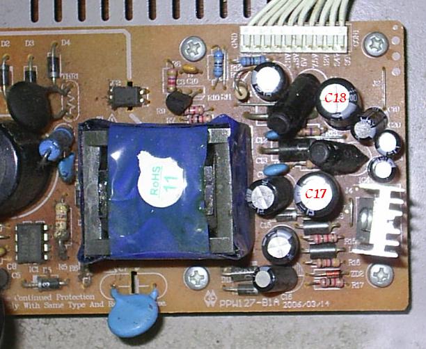
A common fault in the power supply of these receivers causes a flashing 8.8.8.8 to show up on its led display. This is due to a dry electrolytic capacitor that can be replaced at low cost, however you need a soldering iron, tin and some skills soldering electronic circuit boards.
When you open the case you will find two boards inside, the smaller board where power cord plugs in is the power supply. You have to lift this board by removing all screws that hold it in place to work on the solder side. If you have an ESR meter check all electrolytics, otherwise replace the capacitors depicted below.
You have to replace capacitor C18 1000µF 10V and if this does not fix the issue also C17 1000µF 16V. Important! New capacitor must be installed with the same polarity as the original. Capacitors have a vertical stripe pointing to their negative terminal and they must be installed like the originals. In addition the negative terminal is silkscreened on the board as a filled half circle and must match the capacitor stripe side.
If you order a replacement it is recommended to request low ESR 105°C capacitors. They are slightly more expensive but will last longer.
Some units exhibit an intermittent operation of their remote control and it may look like the set top box has poor sensitibity to infrared commands. This problem is due to noise in the infrared sensor ground pin (located on front panel board). The ground plane in this board is poorly designed and the infrared sensor is attached to the same trace of copper that carries all current from the led display to ground. The led display is multiplexed resulting in pulsed current that adds enough noise to disturb its proper operation.
To fix this problem solder a short wire between infrared sensor ground (middle terminal) and ground of its supply capacitor, as shown in the following picture:
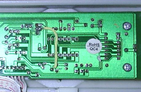
Although nodes connected by this wire are already interconnected by copper traces in the circuit board, this wire stops the led display current pulses from joining the infrared sensor ground and ensure a noise free ground for the sensor.
Project completed on December 2011 by Jeroni Paul.
Copyright © 2011 Jeroni Paul.