| Maintenance & Repair |
| In this section, I will describe some of the repairs and outline some things I've done to my SAAB. The idea is to get plenty of pictures to illustrate the jobs clearly. This is a slow process for me, so keep checking back often. |
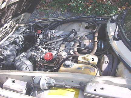
| Here is a fledgling engine bay diagram: |
| Engine Components: A 1984 non-turbo 900S model shown. |
| 1. Oil filler cap/dipstick 2. Brake/clutch fluid reservoir 3. Coolant overflow reservoir 4. Main fusebox 5. Ignition coil 6. Ignition distributor 7. Thermostat housing 8. Fuel pressure warm-up regulator 9. Air intake bellows (air filter to throttle) 10. Relay box 11. Air conditioner recirculation flap 12. Air conditioner compressor 13. Brake system vacuum booster (servo) 14. Fuel injector lines (from fuel distributor) 15. Cruise-control actuator (non-factory dealer installed part) |
| Note: This engine is an 8-valve CIS (K-Jetronic) fuel injected engine, with US specifications. Components vary on international models and later 16V models. |
| Updated: Monday, Aug. 5, 2002 |
| The Brushy Mountain SAAB Page |
 |
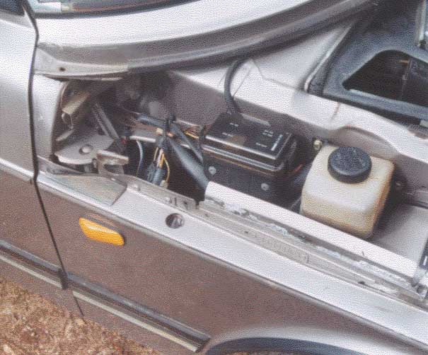 |
| This photo shows the ABS fusebox (1) on the passenger side of 1990-on 900s and the power steering fluid reservoir (2). (1990 16V non-turbo shown). |
| 1 |
| 2 |
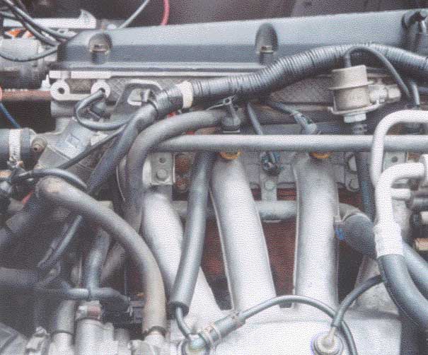 |
| This photo shows several 16V engine components: (1) AIC valve, (2) fuel injector rail, (3) coolant temperature (NTC) sensor, (4) fuel pressure regulator, and (5) throttle position sensor. View is from driver's side of car. (1990 16V non-turbo shown) |
| 1 |
| 2 |
| 4 |
| 5 |
| 3 |