Space Shuttle Facilities 
Introduction Crawler/Transport Launch Control Center (LCC)
Launch Pads 39A and 39B Mobile Launching Platform (MLP) Shuttle Landing Facility (SLF) Shuttle Mate-Demate Device (MDD) Shuttle Carrier Aircraft
Orbital Processing Facility (OPF) Vehicle Assembly Building (VAB)
"The Cape" along with Kennedy Space Center (KSC) is the world's most famous launch site. This site has launched all the major space programs for NASA and also launches commercial rockets; such as the Delta, Atlas, and Titan, at the U.S. Air Force's Cape Canaveral launch pads. Cape Canaveral is a 15-mile-long expanse of land that juts out from the east coast of Florida into the Atlantic Ocean. The natural inhabitants include alligators, mosquitoes, many types of species of birds, and some other unusual types of life. Both the Cape and the KSC are in a state of activity day and night with 12,000 people working constantly to assemble and launch rockets from the ten operation launch pads. Kennedy Space Center (KSC) lies on the northern tip of Merritt Island and is the location for the space shuttle activities and just south of KSC is the Cape, which is run by the 45th Space Wing of the U.S. Air Force. South of the Cape is Port Canaveral were the solid rocket boosters are recovered and it is also the center for tourist cruises. Farther south is Cocoa Beach, where sunbathers may get a grandstand view for launches. The Cape was fist known as the "Long Range Providing Ground for Missile Testing" and first launched a German V-2 missile that was attached to a U.S. WAC-Corporal Upper Stage on July 24, 1950. And America's first satellite, Explorer 1, flew from Launch Pad 26 aboard a Jupiter C booster on January 31, 1958. Since its inception in 1958, Cape Canaveral has launched more than 500 vehicles. Cape Canaveral also has some very interesting aspects to it, which includes the mammoth Vehicle Assembly Building (VAB) which was made to house up to four Saturn 5 rockets and has been known to actually rain inside the building before air conditioners were installed. The Crawler is the world's heaviest and slowest vehicle, which can weight up to 10 million pounds with a fully loaded shuttle and it takes more than 8 hours to complete the 3 to 4 mile journey to the VAB to the pad. The Crawler movers at 1 M.P.H. using four 41-foot-long twin caterpillar tracks that run along a 7-foot-deep crack-proof double-gravel track. The Cape has seen its share of disasters the worst being the Apollo 1 fire on Pad 34 (1967) and the shuttle Challenger explosion which launched from Pad 39B (1986). Cape Canaveral has also had some weather problems, which have mainly came from lightning. In November of 1969, Apollo 12 was hit by lightning as it launched and safely made it to the moon and back, but in 1987 an Atlas Centaur exploded after being bolted by lightning and a freak cold snap was part of the cause of the Challenger tragedy. The Cape can only support a launch from each operation pad every 30 days at best and if a delay springs the whole line in some way is affected. And the Cape has become the prime launch complex even in the future, for example, recently Pad 46 was built to accommodate new types of reusable boosters and has become the first of its kind. Cape Canaveral does have a legacy of left behind it and even today it seems to remain the gateway to the future. Launch Control Center (LCC) 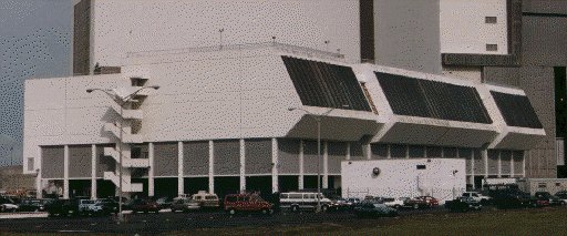 The Launch Control Center (LCC) is a four-story building that is the electronic "brain" of Launch Complex 39. Attached to the southeast corner of the Vehicle Assembly Building (VAB) , it is 5,535 meters (18,159 ft) from Pad 39A . At the time it was constructed, advances in electronics had made it unnecessary to continue locating blockhouses adjacent to launch pads. The first floor contains offices and computer operations. The second floor houses telemetry, RF and tracking, instrumentation, and data reduction and evaluation equipment. The computers of the Central Data Subsystem (CDS), one of the two major components of the Launch Processing System (LPS) that automatically performs most checkout and launch functions, is also on the second floor. The third floor contains the four firing rooms, and each room contains its own copy of the second major component of the Launch Processing System - the Checkout, Control and Monitor Subsystem (CCMS). The system consoles of the CCMS system are manned by the team which oversees all aspects of a checkout and launch operation. Firing rooms 1 and 3 are configured for full control of launch and orbiter operations while Firing room 2 is usually used for software development and testing. Firing room 4 is only a partial firing room and is primarily used as an engineering analysis and support area for launch and checkout operations. The fourth floor of the LCC contains conference rooms, offices and mechanical equipment. The LCC is 23.5 meters (77ft) high, 115.2 meters (378ft) long and 55.1 meters (181 ft) wide. The Launch Control Center (LCC) is a four-story building that is the electronic "brain" of Launch Complex 39. Attached to the southeast corner of the Vehicle Assembly Building (VAB) , it is 5,535 meters (18,159 ft) from Pad 39A . At the time it was constructed, advances in electronics had made it unnecessary to continue locating blockhouses adjacent to launch pads. The first floor contains offices and computer operations. The second floor houses telemetry, RF and tracking, instrumentation, and data reduction and evaluation equipment. The computers of the Central Data Subsystem (CDS), one of the two major components of the Launch Processing System (LPS) that automatically performs most checkout and launch functions, is also on the second floor. The third floor contains the four firing rooms, and each room contains its own copy of the second major component of the Launch Processing System - the Checkout, Control and Monitor Subsystem (CCMS). The system consoles of the CCMS system are manned by the team which oversees all aspects of a checkout and launch operation. Firing rooms 1 and 3 are configured for full control of launch and orbiter operations while Firing room 2 is usually used for software development and testing. Firing room 4 is only a partial firing room and is primarily used as an engineering analysis and support area for launch and checkout operations. The fourth floor of the LCC contains conference rooms, offices and mechanical equipment. The LCC is 23.5 meters (77ft) high, 115.2 meters (378ft) long and 55.1 meters (181 ft) wide.
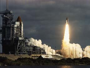 Launch Complex 39's Pad A and Pad B were originally designed to support the Apollo program and were modified for Space Shuttle launch operations. Major changes included the erection of a new Fixed Service Structure (FSS), addition of a Rotating Service Structure (RSS), and the replacement of the Saturn flame deflectors with three new flame deflectors. The upper portion of the Saturn V Launch umbilical tower was removed from two of the Apollo Mobile Launchers and installed at the pad to serve as the FSS. Fuel, oxidizer, high pressure gas, electrical, and pneumatic lines connect the Shuttle vehicle with ground support equipment and are routed through the FSS, RSS and Mobile Launch Platform. Space Shuttle access and servicing at the pad are provided by: FSS - Gaseous Hydrogen Vent Arm for electrical power and for venting hydrogen from the external tank. RSS - Mid-Body Umbilical Unit for fuel cell servicing and life support functions. RSS facilities for loading and off-loading payloads. Hypergolic Umbilical System for servicing the Orbiter systems with fluids and gases. Gaseous Oxygen Vent Arm for preventing ice formation atop the external tank. Orbiter Access Arm (OAA) for crew entrance and exit. MLP - Tail Service Masts for propellant loading and electrical power. The FSS is topped by a 24.4 meter (80ft) tall fiberglass lightning mast grounded by 335 meter (1,100ft) cables that are anchored north and south of the pad. The Mast provides lightning protection for pad structures and the Space Shuttle. The RSS accommodates the loading of payloads vertically at the pad. It is mounted on a semi-circular track which allows it to rotate through an arc of 120 degrees on a radius of 36.6 meters (120 ft). The RSS pivots from a hinge on the FSS until the RSS spacecraft change out room fits flush with the Orbiter's cargo bay. This room allows payloads to be installed or serviced under contamination-free or "clean room" condition. Blast-protected hypergolic storage and supply systems are provided at each pad, and the Launch Processing System (LPS) is used to monitor all aspects of vehicle and payload operations. The LPS system interconnects to the MLP through Hardware Interface Modules (HIM's) located in Pad Terminal Connection Rooms beneath the pads. Pads 39-A and 39-B are virtually identical and roughly octagonal in shape. The distance between pads is 2,657 meters (8,715 ft). The pad base contains 52,000 cubic meters (68,000 cubic yards) of concrete. The ramp leading up to the pad is inclined at a 5% grade. The flame trench is 13 meters (42 ft) deep, 137 meters (450ft) long and 18 meters (58 ft) wide. The orbiter flame deflector is 11.6 meters (38ft) high, 22 meters (72 ft) long and 17.5 meters (57.6 ft) wide. It weights 590,000 kg (1.3 million lbs). The SRB deflector is 12.95 meters (42.5 ft) high, 12.8 meters (42 ft) long and 17.4 meters (57 ft) wide. It weights 499,000 kg (1.1 million lbs). The Sound Suppression Water System is used to protect the launch structure from the intense sound pressure of liftoff. Its water tank is 88.9 meters (290ft) high and has a capacity of 1,135,000 liters (300,000 gallons). There are 6 permanent and 4 extensible pedestals that are used to support the MLP at the pad. Dynamic loads at rebound are 3,175,200 kg (7,000,000 lbs) to 4,762,800 kg (10,500,000lb) at liftoff. The pad is lit with 5 clusters of Xenon high-intensity searchlights (total searchlights: 40) around the pad perimeter. The height of the Fixed Service Structure (FSS) is 105.7 meters (347ft) to the top of the lightning mast (referenced to the pad base) and the Rotating Service Structure (RSS) is 57.6 meters (189ft) high. The Fixed Service Structure (FSS) and Rotating Service Structure (RSS) on Pad 39A underwent a renovation between June and September 1993. Some 13,773 gallons of paint were used on two coats and 1,866 tons of sand were used in the sandblasting operation. The LC-39 Launch complex also contains large liquid oxygen (LOX) and Liquid Hydrogen (LH2) storage tanks. These are large ball-shaped vacuum jacketed dewar bottles used to store super cold cryogenic propellants for the shuttle external tank. The LOX tank, located at the northwest corner of the pad stores 3,406,500 liters (900,000 gallons) of liquid oxygen at a temperature of minus 183 degrees C (-298 F). The LH2 tank is located at the northeast corner of the pad and stores 3,218,250 liters (850,000 gallons) of liquid hydrogen at a temperature of minus 253 degrees C (-423 degrees F). The Weather Protection System protects orbiter tiles from wind blown debris, rain and hail. Wheeled metal doors that ride on steel beams are attached to the Rotating Service Structure and the Fixed Service Structure. Doors slide together (to within 3 inches of each other) between the orbiter's belly and the external tank, providing protection for the lower portion of the orbiter. East Door, attached to the RSS measures 16 meters (53 ft) long, 8 meters (27 ft) tall and weighs 19 metric tons (42,000 lbs). West Door, attached to the FSS measures 13 meters (43 ft) long, 11.6 meters (38ft) tall and weighs 21 metric tons (46,000 lbs) The top of the orbiter is shielded by an inflatable seal extending from the Payload Change out Room forming a semi-circle covering 90 degrees of arc between the orbiter and its external tank. The sides of the orbiter, between the vehicle and the external tank, are protected by a series of 20 metal bi-fold doors that fold out from the Payload Change out Room. The doors measure 24.4 meters by 1.2 meters (80ft x 4ft). There is approximately 1.25 million feet of tubing and piping at Launch Complex 39, varying in sizes from .25 inches to 114 inches in diameter. This is enough pipe to reach from Orlando to Miami. Launch Complex 39's Pad A and Pad B were originally designed to support the Apollo program and were modified for Space Shuttle launch operations. Major changes included the erection of a new Fixed Service Structure (FSS), addition of a Rotating Service Structure (RSS), and the replacement of the Saturn flame deflectors with three new flame deflectors. The upper portion of the Saturn V Launch umbilical tower was removed from two of the Apollo Mobile Launchers and installed at the pad to serve as the FSS. Fuel, oxidizer, high pressure gas, electrical, and pneumatic lines connect the Shuttle vehicle with ground support equipment and are routed through the FSS, RSS and Mobile Launch Platform. Space Shuttle access and servicing at the pad are provided by: FSS - Gaseous Hydrogen Vent Arm for electrical power and for venting hydrogen from the external tank. RSS - Mid-Body Umbilical Unit for fuel cell servicing and life support functions. RSS facilities for loading and off-loading payloads. Hypergolic Umbilical System for servicing the Orbiter systems with fluids and gases. Gaseous Oxygen Vent Arm for preventing ice formation atop the external tank. Orbiter Access Arm (OAA) for crew entrance and exit. MLP - Tail Service Masts for propellant loading and electrical power. The FSS is topped by a 24.4 meter (80ft) tall fiberglass lightning mast grounded by 335 meter (1,100ft) cables that are anchored north and south of the pad. The Mast provides lightning protection for pad structures and the Space Shuttle. The RSS accommodates the loading of payloads vertically at the pad. It is mounted on a semi-circular track which allows it to rotate through an arc of 120 degrees on a radius of 36.6 meters (120 ft). The RSS pivots from a hinge on the FSS until the RSS spacecraft change out room fits flush with the Orbiter's cargo bay. This room allows payloads to be installed or serviced under contamination-free or "clean room" condition. Blast-protected hypergolic storage and supply systems are provided at each pad, and the Launch Processing System (LPS) is used to monitor all aspects of vehicle and payload operations. The LPS system interconnects to the MLP through Hardware Interface Modules (HIM's) located in Pad Terminal Connection Rooms beneath the pads. Pads 39-A and 39-B are virtually identical and roughly octagonal in shape. The distance between pads is 2,657 meters (8,715 ft). The pad base contains 52,000 cubic meters (68,000 cubic yards) of concrete. The ramp leading up to the pad is inclined at a 5% grade. The flame trench is 13 meters (42 ft) deep, 137 meters (450ft) long and 18 meters (58 ft) wide. The orbiter flame deflector is 11.6 meters (38ft) high, 22 meters (72 ft) long and 17.5 meters (57.6 ft) wide. It weights 590,000 kg (1.3 million lbs). The SRB deflector is 12.95 meters (42.5 ft) high, 12.8 meters (42 ft) long and 17.4 meters (57 ft) wide. It weights 499,000 kg (1.1 million lbs). The Sound Suppression Water System is used to protect the launch structure from the intense sound pressure of liftoff. Its water tank is 88.9 meters (290ft) high and has a capacity of 1,135,000 liters (300,000 gallons). There are 6 permanent and 4 extensible pedestals that are used to support the MLP at the pad. Dynamic loads at rebound are 3,175,200 kg (7,000,000 lbs) to 4,762,800 kg (10,500,000lb) at liftoff. The pad is lit with 5 clusters of Xenon high-intensity searchlights (total searchlights: 40) around the pad perimeter. The height of the Fixed Service Structure (FSS) is 105.7 meters (347ft) to the top of the lightning mast (referenced to the pad base) and the Rotating Service Structure (RSS) is 57.6 meters (189ft) high. The Fixed Service Structure (FSS) and Rotating Service Structure (RSS) on Pad 39A underwent a renovation between June and September 1993. Some 13,773 gallons of paint were used on two coats and 1,866 tons of sand were used in the sandblasting operation. The LC-39 Launch complex also contains large liquid oxygen (LOX) and Liquid Hydrogen (LH2) storage tanks. These are large ball-shaped vacuum jacketed dewar bottles used to store super cold cryogenic propellants for the shuttle external tank. The LOX tank, located at the northwest corner of the pad stores 3,406,500 liters (900,000 gallons) of liquid oxygen at a temperature of minus 183 degrees C (-298 F). The LH2 tank is located at the northeast corner of the pad and stores 3,218,250 liters (850,000 gallons) of liquid hydrogen at a temperature of minus 253 degrees C (-423 degrees F). The Weather Protection System protects orbiter tiles from wind blown debris, rain and hail. Wheeled metal doors that ride on steel beams are attached to the Rotating Service Structure and the Fixed Service Structure. Doors slide together (to within 3 inches of each other) between the orbiter's belly and the external tank, providing protection for the lower portion of the orbiter. East Door, attached to the RSS measures 16 meters (53 ft) long, 8 meters (27 ft) tall and weighs 19 metric tons (42,000 lbs). West Door, attached to the FSS measures 13 meters (43 ft) long, 11.6 meters (38ft) tall and weighs 21 metric tons (46,000 lbs) The top of the orbiter is shielded by an inflatable seal extending from the Payload Change out Room forming a semi-circle covering 90 degrees of arc between the orbiter and its external tank. The sides of the orbiter, between the vehicle and the external tank, are protected by a series of 20 metal bi-fold doors that fold out from the Payload Change out Room. The doors measure 24.4 meters by 1.2 meters (80ft x 4ft). There is approximately 1.25 million feet of tubing and piping at Launch Complex 39, varying in sizes from .25 inches to 114 inches in diameter. This is enough pipe to reach from Orlando to Miami.
Mobile Launcher Platform (MLP) 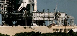 The three Mobile Launchers used in Apollo/Saturn operations were modified for use in Shuttle operations. With cranes, umbilical towers, and swing arms removed, the Mobile Launchers were redesigned Mobile Launcher Platforms (MLP). In place of one large opening in the platform, three smaller openings accommodate flames and hot exhaust gases from the solid rocket boosters and the orbiter engines. Segments of the dismantled umbilical towers are part of the permanent installation at the launch pad, where they serve as sections of the Fixed Service Structure (FSS). A third Apollo umbilical tower, removed from MLP-3, has been cut into 20 ft sections and placed in a field in the KSC industrial area. It may someday become reconstructed as part of the KSC tour route. Tail Service Masts (TSM's), one on each side of the main engines exhausts hole provide umbilical connections for fuel and oxidizer, gases, ground electrical power and communications links. These Masts are 4.6m (15ft) long, 2.7m (9ft) wide and 9.4m (31 ft) high. The three Mobile Launchers used in Apollo/Saturn operations were modified for use in Shuttle operations. With cranes, umbilical towers, and swing arms removed, the Mobile Launchers were redesigned Mobile Launcher Platforms (MLP). In place of one large opening in the platform, three smaller openings accommodate flames and hot exhaust gases from the solid rocket boosters and the orbiter engines. Segments of the dismantled umbilical towers are part of the permanent installation at the launch pad, where they serve as sections of the Fixed Service Structure (FSS). A third Apollo umbilical tower, removed from MLP-3, has been cut into 20 ft sections and placed in a field in the KSC industrial area. It may someday become reconstructed as part of the KSC tour route. Tail Service Masts (TSM's), one on each side of the main engines exhausts hole provide umbilical connections for fuel and oxidizer, gases, ground electrical power and communications links. These Masts are 4.6m (15ft) long, 2.7m (9ft) wide and 9.4m (31 ft) high.
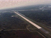 Orbiter landings at the Kennedy Space Center are made on one of the largest runways in the world. The runway is located 3.2 km (2 miles) northwest of the Vehicle Assembly Building and is 4,572 meters (15,000ft) long and 91.4 meters (300ft) wide - about as wide as the length of a football field. It has 305 meters (1000ft) of paved overruns at each end and the paving thickness is 40.6cm (15 inches) at the center. The facility includes a 150 x 168 meter (490x550ft) parking apron and a 3.2 km (2 mile) tow-way connecting it with the Orbiter Processing Facility . Located adjacent to the parking apron is a Landing Aids Control Building (LACB) which supports landing operations and houses operations personnel. Located at the northeast corner of the parking apron is the Mate/De-Mate device (MDD) used to raise and lower the orbiter from its 747 carrier aircraft during ferry operations. The open-truss steel structure is equipped with hoists, adapters and movable platforms for access to certain orbiter components and equipment. It also is equipped with lightning protection devices. The MDD is 45.7 meters (150ft) long, 28.3 meters (93ft) wide and 32 meters (105ft) high. The Shuttle Landing Facility is equipped with a number of navigation and landing aids to assist Shuttle pilots in landing. There are four sophisticated Microwave Scanning Beam Landing System (MSBLS) ground stations - two located at each end of the runway - that provide elevation and directional/distance measurement for landing approaches from the northwest (runway 15) or southeast (runway 33). Equipment onboard the orbiter receives the data from the MSBLS stations and automatically makes any needed adjustments to the glide slope. A Tactical Air Navigation (TACAN) system, located at mid-field off the east side of the runway, is used by pilots to execute an instrument landing approach to the runway. The TACAN has a range of 483 kilometers (300 miles), and is received by the orbiter when it emerges from the reentry blackout period. The final approach is guided by the MSBLS system. Visual aids are provided by Precision Approach Path Indicators, known as the PAPI system. They utilize arrays of red and white lights that, when lined up properly by the pilot, will indicate the proper glide slope. A ball/bar light system is used for inner glide slope information on final approach - to inform the pilot whether he is on, above or below the glide slope for an orbiter touchdown point marked on the runway. A Recovery Convoy Staging Area, located just east of the runway about midway along its length, houses trailers, mobile units and specially designed vehicles that are used to "safe" the orbiter immediately after landing for crew egress and transfer of the orbiter to the Orbiter Processing Facility. A specially constructed earthen mound just east of the Convoy Staging Area contains bleachers, press facilities and a Public Affairs control room to support invited guests and press coverage during orbiter landings at the Kennedy Space Center. Orbiter landings at the Kennedy Space Center are made on one of the largest runways in the world. The runway is located 3.2 km (2 miles) northwest of the Vehicle Assembly Building and is 4,572 meters (15,000ft) long and 91.4 meters (300ft) wide - about as wide as the length of a football field. It has 305 meters (1000ft) of paved overruns at each end and the paving thickness is 40.6cm (15 inches) at the center. The facility includes a 150 x 168 meter (490x550ft) parking apron and a 3.2 km (2 mile) tow-way connecting it with the Orbiter Processing Facility . Located adjacent to the parking apron is a Landing Aids Control Building (LACB) which supports landing operations and houses operations personnel. Located at the northeast corner of the parking apron is the Mate/De-Mate device (MDD) used to raise and lower the orbiter from its 747 carrier aircraft during ferry operations. The open-truss steel structure is equipped with hoists, adapters and movable platforms for access to certain orbiter components and equipment. It also is equipped with lightning protection devices. The MDD is 45.7 meters (150ft) long, 28.3 meters (93ft) wide and 32 meters (105ft) high. The Shuttle Landing Facility is equipped with a number of navigation and landing aids to assist Shuttle pilots in landing. There are four sophisticated Microwave Scanning Beam Landing System (MSBLS) ground stations - two located at each end of the runway - that provide elevation and directional/distance measurement for landing approaches from the northwest (runway 15) or southeast (runway 33). Equipment onboard the orbiter receives the data from the MSBLS stations and automatically makes any needed adjustments to the glide slope. A Tactical Air Navigation (TACAN) system, located at mid-field off the east side of the runway, is used by pilots to execute an instrument landing approach to the runway. The TACAN has a range of 483 kilometers (300 miles), and is received by the orbiter when it emerges from the reentry blackout period. The final approach is guided by the MSBLS system. Visual aids are provided by Precision Approach Path Indicators, known as the PAPI system. They utilize arrays of red and white lights that, when lined up properly by the pilot, will indicate the proper glide slope. A ball/bar light system is used for inner glide slope information on final approach - to inform the pilot whether he is on, above or below the glide slope for an orbiter touchdown point marked on the runway. A Recovery Convoy Staging Area, located just east of the runway about midway along its length, houses trailers, mobile units and specially designed vehicles that are used to "safe" the orbiter immediately after landing for crew egress and transfer of the orbiter to the Orbiter Processing Facility. A specially constructed earthen mound just east of the Convoy Staging Area contains bleachers, press facilities and a Public Affairs control room to support invited guests and press coverage during orbiter landings at the Kennedy Space Center.
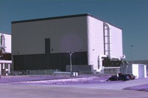 Immediately after landing, the orbiter is towed to the Orbiter Processing Facility (OPF) located west of the Vehicle Assembly Building (VAB) . The orbiter then undergoes safety procedures in the OPF which include removing residual fuels and explosive ordnance items. Then the orbiter's previous mission payloads are removed and the vehicle is fully inspected, tested, and refurbished for its next mission. These functions require approximately two-thirds of the time between missions. The remainder is devoted to the installation and checkout of the payload for the next mission. Power-up testing of orbiter vehicles in the OPF are actually controlled from consoles in the Launch Control Complex (LCC) . OPF-1 and OPF-2 consist of two 2,700 sq meter (29,000 sq ft) high bays and are separated by a 2,130 sq meter (23,600 sq ft) low bay while OPF-3 is across the street. OPF-3 was previously called the Orbiter Maintenance & Refurbishment Facility (OMRF) but has been upgraded to a fully functioning Orbiter Processing Facility. OPF-3 is located across the street from OPF-1 and OPF-2. It is 4,645 sq meters (50,000 sq ft) facility. It consists of a high bay 29 meters high (95 ft) high and a two-story low bay area. Immediately after landing, the orbiter is towed to the Orbiter Processing Facility (OPF) located west of the Vehicle Assembly Building (VAB) . The orbiter then undergoes safety procedures in the OPF which include removing residual fuels and explosive ordnance items. Then the orbiter's previous mission payloads are removed and the vehicle is fully inspected, tested, and refurbished for its next mission. These functions require approximately two-thirds of the time between missions. The remainder is devoted to the installation and checkout of the payload for the next mission. Power-up testing of orbiter vehicles in the OPF are actually controlled from consoles in the Launch Control Complex (LCC) . OPF-1 and OPF-2 consist of two 2,700 sq meter (29,000 sq ft) high bays and are separated by a 2,130 sq meter (23,600 sq ft) low bay while OPF-3 is across the street. OPF-3 was previously called the Orbiter Maintenance & Refurbishment Facility (OMRF) but has been upgraded to a fully functioning Orbiter Processing Facility. OPF-3 is located across the street from OPF-1 and OPF-2. It is 4,645 sq meters (50,000 sq ft) facility. It consists of a high bay 29 meters high (95 ft) high and a two-story low bay area.
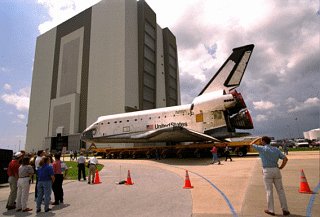 The Vehicle Assembly Building (VAB) is one of the largest buildings in the world. It was originally built for assembly of Apollo/Saturn vehicles and was later modified to support Space Shuttle operations. High Bays 1 and 3 are used for integration and stacking of the complete Space Shuttle vehicle. High Bay 2 is used for external tank (ET) checkout and storage and as a contingency storage area for orbiters. High Bay 4 is also used for ET checkout and storage, as well as for payload canister operations and solid rocket booster (SRB) contingency handling. The Low Bay area contains Space Shuttle main engine maintenance and overhaul shops, and serves as a holding area for SRB forward assemblies and aft skirts. During Space shuttle build-up operations inside the VAB, integrated SRB segments are transferred from near bay SRB assembly and checkout facilities, hoisted onto a Mobile Launcher Platform in High Bays 1 or 3 and mated together to form two complete SRB's. The ET, after arrival by barge, is inspected and checked out in High Bays 2 or 4 and then transferred to High Bay's 1 or 3 to be attached to the SRBs already in place. The orbiter is then towed over from the Orbiter Processing Facility to the VAB transfer aisle, raised to a vertical position, lowered onto the Mobile Launcher Platform and then mated to the rest of the stack. When assembly and checkout is complete, the crawler-transporter enters the High Bay, picks up the platform and assembled shuttle vehicle and carries them to the launch pad. The VAB covers 3.25 hectares (8 acres). It is 160 meters (525 ft) tall, 218 meters (716 ft) long and 158 meters (518 ft) wide. It encloses 3,664,883 cubic meters (129,428,000 cubic feet) of space. The Vehicle Assembly Building (VAB) is one of the largest buildings in the world. It was originally built for assembly of Apollo/Saturn vehicles and was later modified to support Space Shuttle operations. High Bays 1 and 3 are used for integration and stacking of the complete Space Shuttle vehicle. High Bay 2 is used for external tank (ET) checkout and storage and as a contingency storage area for orbiters. High Bay 4 is also used for ET checkout and storage, as well as for payload canister operations and solid rocket booster (SRB) contingency handling. The Low Bay area contains Space Shuttle main engine maintenance and overhaul shops, and serves as a holding area for SRB forward assemblies and aft skirts. During Space shuttle build-up operations inside the VAB, integrated SRB segments are transferred from near bay SRB assembly and checkout facilities, hoisted onto a Mobile Launcher Platform in High Bays 1 or 3 and mated together to form two complete SRB's. The ET, after arrival by barge, is inspected and checked out in High Bays 2 or 4 and then transferred to High Bay's 1 or 3 to be attached to the SRBs already in place. The orbiter is then towed over from the Orbiter Processing Facility to the VAB transfer aisle, raised to a vertical position, lowered onto the Mobile Launcher Platform and then mated to the rest of the stack. When assembly and checkout is complete, the crawler-transporter enters the High Bay, picks up the platform and assembled shuttle vehicle and carries them to the launch pad. The VAB covers 3.25 hectares (8 acres). It is 160 meters (525 ft) tall, 218 meters (716 ft) long and 158 meters (518 ft) wide. It encloses 3,664,883 cubic meters (129,428,000 cubic feet) of space.
Flag & Bicentennial Emblem: Added in 1976, required 6,000 gallons of paint. The flag is 64 x 33.5 meters (209 x 110 ft) in size. Each strip on the flag is as big as the tour buses used to transport visitors around KSC Steel: 89,421 metric tons (98,590 tons) Concrete: 49,696 cubic meters (65,000 cubic yards) Piling: 4,225 open-end steel pipe piles, 0.4 meters (16 inches) in diameter were driven 49 meters (160 ft) into bedrock. Air Conditioning: 9,070 metric tons (10,000 tons), 125 ventilators. Lifting Devices: 71 cranes; two 227 metric ton (250 ton) bridge cranes. Siding: 100,800 sq meters (1,085,000 sq ft) insulated aluminum panels; 6,503 sq meters (70,000 sq ft) plastic panels. Doors: There are 4 High Bay doors. Each opening is 139 meters (456 ft) high. The north entry to the transfer aisle was widened 12.2 meters (40 ft) to permit entry of the Orbiter, and slotted at the center to accommodate its vertical stabilizer. 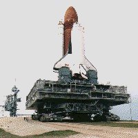 The two tracked Crawler-Transporters previously used to move the assembled Apollo/Saturn from the VAB to the launch pad are now used for transporting Shuttle vehicles. The two tracked Crawler-Transporters previously used to move the assembled Apollo/Saturn from the VAB to the launch pad are now used for transporting Shuttle vehicles.
Weight: 2,721 metric tons (6 million pounds) Length: 40 meters (131 ft) wide, 35 meters (114ft) long Miles: 2,526 miles (1,243 miles since 1977) KSC has 2 crawler-transporters. Each vehicle consists of four double-tracked crawlers, each 3 meters (10 ft) high and 12 meters (41 ft) long. Each of the 8 tracks on a vehicle contains 57 shoes per track and each tread shoe weighs about .9 metric tons (one ton). Click here to see the crawler moving a shuttle . The Crawler/Transporter is powered by 16 traction motors powered by four 1,000 kw generators, driven by two 2,750hp diesel engines. Two 750 kw generators, driven by two 1,065 hp diesel engines are used for jacking, steering, lighting, and ventilating. Two 150 kw generators are also used for MLP power. The KSC crawlers are the largest tracked vehicles known. They move the Mobile Launcher Platform into the Vehicle Assembly Building and then to the Launch Pad with an assembled space vehicle. Maximum speed is 1.6km (one mile) per hour loaded, about 3.2 km (2 miles) per hour unloaded. Launch Pad to VAB trip time with the Mobile Launch Platform is about 5 hours. The crawler burns 568 liters (150 gallons) of diesel oil per mile. The top of the orbiter is kept vertical within plus or minus 10 minutes of arc, about the diameter of a basketball during the journey. Leveling systems within the crawler keeps the platform level while negotiating the 5% ramp leading up to the pad surface. The height of the crawler is 6 meters (20ft) to 8 meters (26 feet) adjustable. The top deck is flat and square, about the size of a baseball infield, 27 meters (90 feet) on a side. Two operator control cabs, one at each end of the chassis, are used to control all crawler systems. KSC's two crawler-transporters have accumulated 1,243 miles since 1977. Including the Apollo years, the transporters have racked up 2,526 miles, about the same distance as a one-way trip from KSC to Los Angeles by interstate highway or a round trip between KSC and New York City. 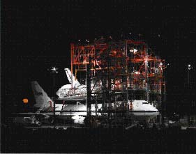 The Space Shuttle Mate-Demate Device (MDD) at NASA's Dryden Flight Research Center, Edwards, Calif., is a large, gantry-like, steel structure used to hoist the orbiters off the ground during post-landing servicing operations and during mating and demating operations with the 747 Shuttle Carrier Aircraft (SCA). The Space Shuttle Mate-Demate Device (MDD) at NASA's Dryden Flight Research Center, Edwards, Calif., is a large, gantry-like, steel structure used to hoist the orbiters off the ground during post-landing servicing operations and during mating and demating operations with the 747 Shuttle Carrier Aircraft (SCA).
Construction of the MDD was completed in late 1976. It was first used during mate-demate operations with the prototype orbiter Enterprise during the Approach and Landing Tests (ALT) in 1977. It has been used for all post-landing and SCA mating operations at Dryden since the ALT program. The facility consists of two 100-foot towers with stationary work platforms at the 20 40 60 and 80-foot levels on each tower and a horizontal structure mounted at the 80-foot level between the two towers. The horizontal unit cantilevers 70 feet out from the main tower units and controls and guides a large lift beam that attaches to the orbiters to raise and lower them. Three large hoists are used to raise and lower the lift beam. Two of the hoists are connected to the aft portion of the lift beam and one hoist is attached to the beam's forward section. The three hoists operate simultaneously in the hoisting process. Each of the three hoists has a 100,000-pound lift capability. Operating together, the total lifting capacity of the three units is 240,000 pounds (120 tons). During orbiter turnaround operations, two access platforms for orbiter servicing specialists are positioned on each side of the orbiter after it is towed into the MDD. The platforms are normally stored at the 60-foot level when not in use. During servicing operations the platforms are lowered on each side of the orbiter by a pair of telescoping tubes extending down from the cantilever section. Two equipment hoists, each capable of lifting 10,000 pounds are also built into each tower. These hoists operate up to the 60-foot level of the MDD. Connell Associates Inc., Coral Gables, Fla. designed the MDD. It was constructed in 1976 by the George A. Fuller Co., Chicago, Ill., at a cost of $1.7 million. The Space Shuttle hangar, near the MDD, is a single-bay 25,000 square-foot structure 170 feet deep, 140 feet wide and 80 feet high. A 6,700 square-foot annex on the north side of the hangar building is used for administrative offices, ground operations control room and a joint-use shop area. Inside the hangar, two overhead bridge cranes provide lift capability for orbiter (or aircraft) servicing and maintenance operations. Each crane has a lift capability of 50,000 pounds. Voorheis, Trindle and Nelson (VTN), Irvine, Calif. Built the hangar. It was built by Santa Fe Engineers Inc., Lancaster, Calif., at a cost of $3.7 million. Construction was completed in early 1976. A concrete tow-way, 60 feet wide and 15 inches thick, connects the MDD and the Space Shuttle hangar with the aircraft ramp at the main Dryden complex, and with the taxiway extending onto the Edwards Air Force Base flightline and runway network. Shuttle Carrier Aircraft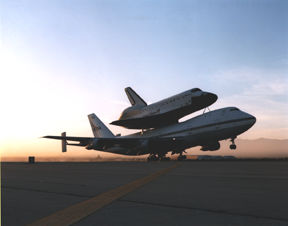 NASA uses two modified Boeing 747 jetliners, originally manufactured for commercial use, as Space Shuttle Carrier Aircraft (SCA). One is a 747-100 model, while the other is designated a 747-100SR (short range). The two aircraft are identical in appearance and in their performance as Shuttle Carrier Aircraft. NASA uses two modified Boeing 747 jetliners, originally manufactured for commercial use, as Space Shuttle Carrier Aircraft (SCA). One is a 747-100 model, while the other is designated a 747-100SR (short range). The two aircraft are identical in appearance and in their performance as Shuttle Carrier Aircraft.
The 747 series of aircraft are four-engine intercontinental-range, swept-wing "jumbo jets" that entered commercial service in 1969. The SCAs are used to ferry space shuttle orbiters from landing sites back to the launch complex at the Kennedy Space Center and also to and from other locations too distant for the orbiters to be delivered by ground transportation. The orbiters are placed atop the SCAs by Mate-Demate Devices, large gantry-like structures that hoist the orbiters off the ground for post-flight servicing, and then mate them with the SCAs for ferry flights. Features which distinguish the two SCAs from standard 747 jetliners are: -Three struts with associated interior structural strengthening protrude from the top of the fuselage (two aft, one forward) on which the orbiter is attached. - Two additional vertical stabilizers, one on each end of the standard horizontal stabilizer, to enhance directional stability. - Removal of all interior furnishings and equipment aft of the forward No. 1 doors. - Instrumentation used by SCA flight crews and engineers to monitor orbiter electrical loads during the ferry flights and also during pre- and post-ferry flight operations. - The two SCAs are under the operational control of NASA's Johnson Space Center, Houston, TX. NASA 905 was the first SCA. It was obtained from American Airlines in 1974. Shortly after it was accepted by NASA it was flown in a series of wake vortex research flights at the Dryden Flight Research Center in a study to seek ways of reducing turbulence produced by large aircraft. Pilots flying as much as several miles behind large aircraft have encountered wake turbulence that have caused control problems. The NASA study helped the Federal Aviation Administration modify flight procedures for commercial aircraft during airport approaches and departures. Following the wake vortex studies, NASA 905 was modified by Boeing to its present SCA configuration and the aircraft was returned to Dryden for its role in the 1977 Space Shuttle Approach and Landing Tests (ALT). This series of eight captive and five free flights with the orbiter prototype Enterprise, in addition to ground taxi tests, validated the aircraft's performance as an SCA, in addition to verifying the glide and landing characteristics of the orbiter configuration paving the way for orbital flights. A flight crew escape system, consisting of an exit tunnel extending from the flight deck to a hatch in the bottom of the fuselage, was installed during the modifications. The system also included a pyrotechnic system to activate the hatch release and cabin window release mechanisms. The flight crew escape system was removed from the NASA 905 following the successful completion of the ALT program. NASA 905 was the only SCA used by the space shuttle program until Nov. 1990, when NASA 911 was delivered as an SCA. Along with ferrying Enterprise and the flight rated orbiters between the launch and landing sites and other locations, NASA 905 also ferried Enterprise to Europe for display in England and at the Paris Air Show. The second SCA is designated NASA 911. It was obtained by NASA from Japan Airlines (JAL) in 1989. It was also modified by Boeing Corporation. It was delivered to NASA Nov. 20, 1990. Wingspan: 195 ft. 8 in. Length: 231 ft. 10 in. Height: Top of vertical stabilizer, 63 ft. 5 in.; To top of cockpit area, 32 ft. 1 in. Weight: Basic weight, NASA 905, 318,053 lbs- NASA 911, 323,034 lbs; Maximum gross taxi weight, 713,000 lbs; maximum gross brake release weight, 710,000 lbs; maximum gross landing weight, 600,000 lbs Power Plant: Four Pratt and Whitney JT9D-7J gas turbine engines, each producing 50,000 lbs of thrust Airspeed limits with, and without an orbiter: 250 knots or Mach 0.6 Altitude: Typical cruise with orbiter, 13,000-15,000 ft MSL; typical cruise unmated, 24,000-26,000 ft MSL. Minimum temperature at altitude 15 degrees (F) (-9 degrees C) or 8 psi ambient pressure Range: Typical mated, 1000 nautical miles (with reserves); maximum unmated, 5500 nautical miles Fuel: 47,210 gallons (316,307 lbs) jet fuel Minimum for flight is two pilots and one flight engineer. Minimum for mated flight is two pilots and two flight engineers. **All information is found in the NSTS Shuttle Reference Manual (1988) & NASA Dryden Research Center** |