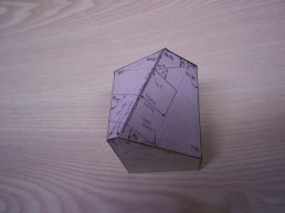
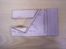
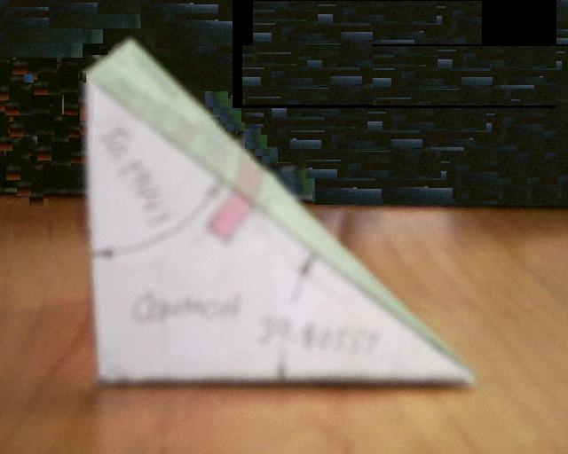
Valley Foot meets Common Rafter
Preliminary
compound
angle cuts and layout
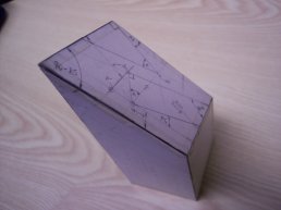
Bottom shoulder: Miter = R4P , Blade Angle = A5P
Plumb Face: Miter = 90 - R1 , Blade Angle = DD
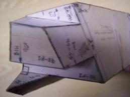
Valley Foot meets Common Rafter
Compound angle and housing chamfers
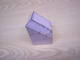
Chamfers
are perpendicular to the compound face
Tenon: Valley Foot meets Common Rafter
Tenon is perpendicular to the compound face
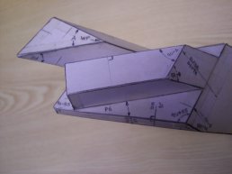
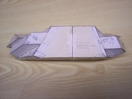
Common Rafter section showing
mortise to receive tenon at Valley Foot
Main Pitch angle SS at rafter foot is to the right
Housing angle to bottom edge of rafter = P6
|
The housing angle for the related joint
Valley Foot meets Wall
slopes at R5P with respect to level.
|
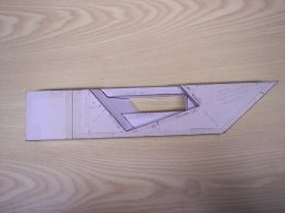
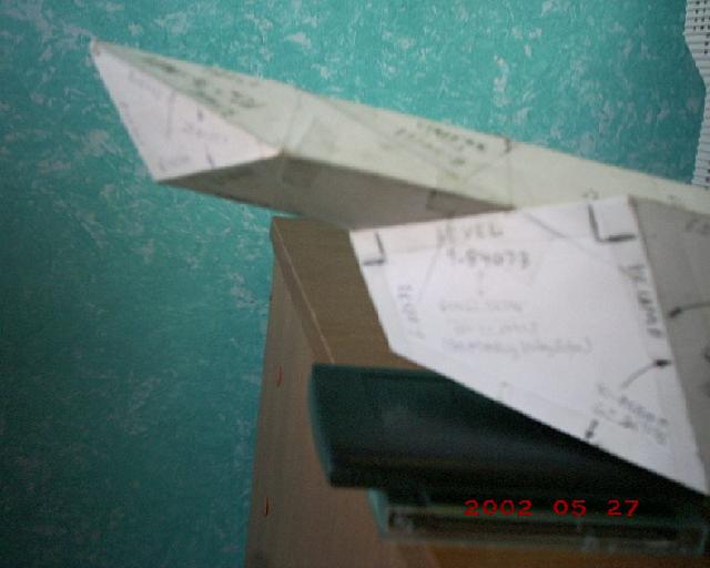
Valley Peak meets Main Purlin
Preliminary compound angle cuts and layout
|
The tenon in the following two views is cut square with respect to the compound face
to the left in the image above.
|
Valley Peak meets Main Purlin
View of Tenon from bottom shoulder
Valley Peak meets Main Purlin
View of tenon on Valley meets Valley side

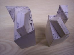
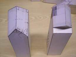
Side Views of Valley Tenons
Left: Foot meets Common Rafter
Right: Peak meets Main Purlin
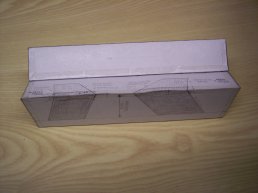
End Views of Valley Tenons
Left: Peak meets Main Purlin
Right: Foot meets Common Rafter
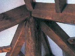
Mortise: Valley Peak meets Main Purlin
|
A jig similar in shape to the housing illustrated above was used to project the layout for
the mortise "on the round" to achieve the joint in the image below.
|
Mortise: Valley Peaks meet at Main Purlin
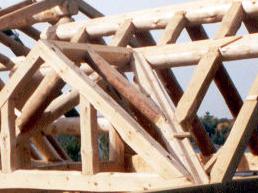
The following sets of images depict models of the joinery required for
Valleys meet at Center Post
Ridge Beams meet Valley
Purlins meet Valley
|
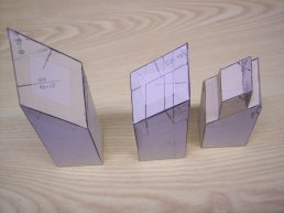
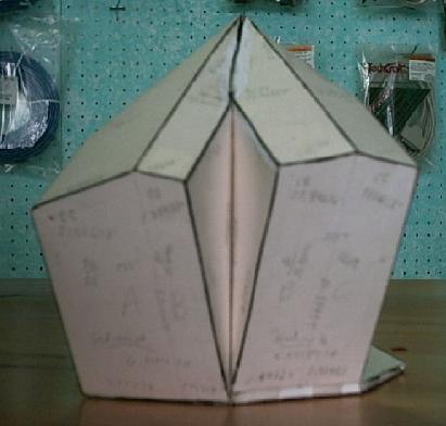
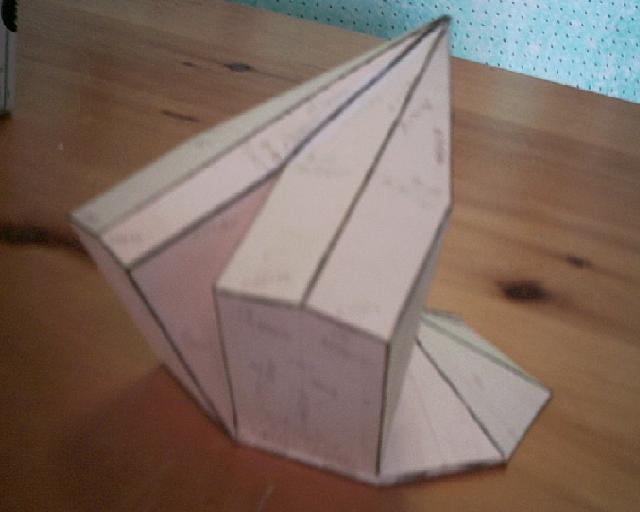
Models of Valley Roof Sections
Valley Peaks meet at Center Post
Left: Preliminary compound angle cuts
Right: Bird's-Mouth cut for Center Post
Valley Section: the peak is to the left
Backing angle and Mortise layouts
Left: Jack Purlin Right: Jack Rafter
Compound Angles and Tenon Layouts
Left: Jack rafter compound angle
Center:
Jack purlin compound angle
Right: Jack Purlin tenon layout. The shaded areas shown on the model to
the right will be removed,
square cutting
the bottom face of the tenon.
|
Valley Peak meets Ridge Beam
Sketch of Intersection
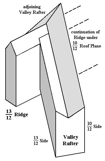
Main Pitch: 10/12
Adjacent Pitch: 13/12
Angle viewded in plan between ridge lines: 90°
Plan View of Intersection
Preliminary compound angles and layout
Valley with Backing Angles
and finished faces at peak
Valley with Backing Angles
and finished faces at peak
Irregular Hips meet at Center Post
Plan: Irregular Octagon
Common Pitches
Left Hip rafter, Left Side: 8 9/16 ÷ 12
between Hip rafters Center: 7 17/32 ÷ 12
Right Hip rafter, Right Side: 7 1/2 ÷ 12
|
The Hip rafters are offset to make the post intercept the long axes of the Hip rafters at right angles.
|
Models of
Square Tail Fascia intersection with Hip Rafter