 |
|
|
|
|
|
|
|
|
|
|
|
|
|
|
|
|
|
|
|
|
|
|
|
|
|
|
|
|
|
|
|
|
|
|
|
|
|
|
|
|
|
|
|
|
|
|
|
|
 |
|
|
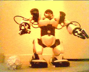
ROBOSAPIEN |
|
|
|
IR CONTROL |
|
|
|
|

|
|
|
|
|
 |
|
|
|
|
|
|
|
|
  |
|
|
|
|
|
|
 |
|
|
|
Home |
|
Robosapien |
|
Pictures |
|
Videos |
|
Modify |
|
Links |
|
|
|
|
|
|
Glitch |
|
Tricks |
|
IR Control |
|
|
|
About Me |
|
|
|
|
|
|
|
|
|
|
|
|
|
|
|
|
|
First off, I warn that completely replacing the RS brain should only be attempted by those with a lot of time, electronic skills, and programming ego. You don't have to though -- if you carefully remove the connectors and lift the RS motherboard, on the back you will find all inputs and outputs labeled next to gold pads convenient for soldering interface wires. |
|
|
|
- M means motors,
- P means input or output port,
- VDD is raw battery voltage (caution: fluctuates wildly)
- Vcc is regulated 3.6v (100mA but don't overload it)
- Gnd is universal ground. |
|
|
|
The only way to input commands is by direct serial input to the IR-OUT pin (active low signals, 1200bps), and through the P1.4 (right) and P1.1 (left) touch sensors. In three I/O ports, you have his entire body now under control. |
|
|
|
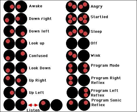
The 6 outputs for the eyes (P2.0 to P2.5) can be used as a very effective digital-level feedback source. If you look carefully, you'll see his eyes give distinct patterns for all conditions. Mapping these will tell your uP everything it needs about what the robot is doing. |
|
|
|
The chest area is mostly empty space and ideal for mounting any brain add-ons. However, glue tinfoil (or equivalent) across his sternum first so the waist and shoulder motors do not cause interference. |
|
|
|
Most of the secret I/R codes are designed so that a controlling computer can cause him to dovetail commands very quickly (up to 30 baud) and even be programmed at very high rates from a nearby I/R port. Some people will already have noticed that it is possible to move the robot by the remote faster than he can move himself. Taken to the limit, the robot can be a very responsive "horse" to any uP controller or I/R equipped PDA or laptop. |
|
|
|
Posted by M. W. Tilden |
|
|
|
Conection Pin-out |
|
|
|
Label Side / Location Connects to
M1 Left Elbow motor (and opens gripper)
M2 Left Shoulder motor
M3 Right Elbow motor (and opens gripper)
M4 Right Shoulder motor
M5 Tilt body motor
M6 Left Leg/Hip motor
M7 Right Leg/Hip motor
P1.1 Left Arm Finger switch
P1.2 Left Arm Elbow position switch
P1.3 Left Shoulder Position switch
P1.4 Right Arm Finger switch
P1.5 Right Arm Elbow position switch
P1.6 Right Shoulder Position switch
P2.0 Left Eye LED (-)
P2.1 Left Eye LED (-)
P2.2 Left Eye LED (-)
P2.3 Right Eye LED (-)
P2.4 Right Eye LED (-)
P2.5 Right Eye LED (-)
Vcc Common Vcc for all eye LEDs
P2.6 Left Arm LED (-)
P2.7 Right Arm LED (-)
SPK1 & SPK2 Speaker on back
VDD-IN Batteries in feet (caution: fluctuates wildly)
GND Common Ground IR-OUT IR receiver in head Active low signals, 1200bps
Vcc Regulated 3.6v (100mA but don't overload it) |
|
|
|
 |
|
|
|